background image

Pg.39

Model G0834 (Mfd. Since 12/17)

-41-

4.

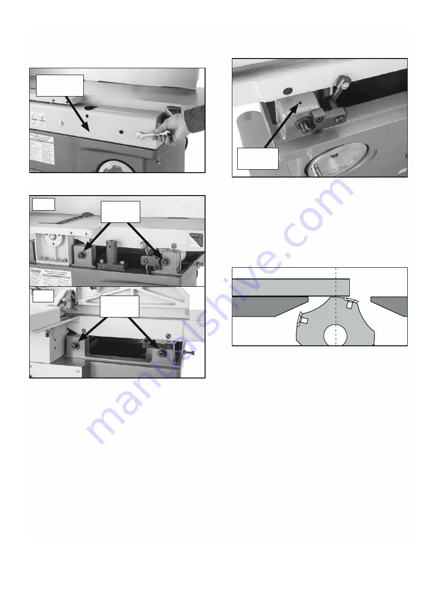
  Remove  front  and  rear  table  covers  to 

expose  eccentric  bushings,  as  shown  in 

Figures 54–55

.

5.

  Loosen set screw on each eccentric bushing 

(see 

Figure 56

).

Figure 56.

 Location of eccentric bushing set 

screw.

Figure 54.

 Removing front table cover.

Front Table 

Cover

Straightedge 

Outfeed Table 

Figure 57.

 Adjusting outfeed table even with 

cutterhead body.

Figure 55.

 Locations of front and rear eccentric 

bushings.

Eccentric 
Bushings

Front

Rear

Eccentric 
Bushings

6.

  Place  straightedge  on  outfeed  table  so  it 

hangs over cutterhead, rotate motor pulley so 
straightedge  is  between  inserts,  then  lower 
outfeed  table  until  straightedge  just  touches 
cutterhead body, as shown in 

Figure 57

.

Set Screw 

(1 of 4)

Summary of Contents for JN-XC300C

Page 1: ...CARBATEC COM AU J N X C 3 0 0 C M A N U A L 300mm Helical Head Jointer 3...

Page 2: ...ements more accessible to Aussie woodworkers Backed by our no fuss after sales care and warranty support you can trust Carbatec to keep you woodworking as promised We look forward to sharing in your w...

Page 3: ...ms shipped with your machine Before beginning setup lay these items out and inventory them If any non proprietary parts are missing e g a nut or a washer we will gladly replace them or for the sake of...

Page 4: ...f purchase in your manual for future reference 3 Made in for CARBATEC PTY LTD Brisbane Australia Model Voltage Freq Phase Amp kW Speed Lot No Serial No Date QUALITY INSPECTED Key information can be fo...

Page 5: ...is manual including all safety alert symbols such as DANGER WARNING and CAUTION before using this tool Failure to following all instructions listed below may result in electric shock fire and or serio...

Page 6: ...intended applications 3 GROUND ALL TOOLS If the tool is supplied with a 3 prong plug it must be plugged into a 3 contact electrical receptacle The third prong is used to ground the tool and provide p...

Page 7: ...guard or other part that is damaged should be immediately repaired or replaced 12 DO NOT OPERATE TOOL WHILE TIRED OR UNDER THE INFLUENCE OF DRUGS MEDICATION OR ALCOHOL 13 SECURE ALL WORK Use clamps or...

Page 8: ...can increase risk of kickback It also requires more cutting force which produces chat ter or excessive chip out Always joint or surface plane WITH the grain CUTTING LIMITATIONS Cutting workpieces that...

Page 9: ...ellow stripes is the equipment grounding conductor DO NOT connect the equipment grounding conductor to a live terminal if repair or replacement of the electric cord or plug is necessary CHECK WITH A Q...

Page 10: ...planing material thinner than 3 e Never perform jointing planing or rabbeting cuts on pieces shorter than 14 in length Become familiar with the names and locations of the controls and features shown...

Page 11: ...570 546 9663 IMPORTANT Save all packaging materials until you are completely satisfied with the machine and have resolved any issues between Grizzly or the shipping agent You MUST have the original pa...

Page 12: ...operly adjusted so it is even with highest point of cutterhead insert rotation aka TDC Refer to Page 37 for more details E Fence Supports workpiece laterally as it moves across cutterhead determines a...

Page 13: ...sition in available tilt range Fence Controls K Depth of Cut Scale Indicates depth of cut per pass L Infeed Positive Stop Bolt Allows operator to quickly adjust the infeed table to perform heavy or li...

Page 14: ...orks well Safety glasses disposable gloves Plastic paint scraper optional Basic steps for removing rust preventative 1 Put on safety glasses 2 Coat the rust preventative with a liberal amount of clean...

Page 15: ...ment The physical environment where the machine is operated is important for safe operation and lon gevity of machine components For best results operate this machine in a dry environment that is free...

Page 16: ...xt step DO NOT attempt to lift or move jointer without using proper lifting equipment such as forklift or crane or necessary assistance from other people Each piece of lifting equipment must be rated...

Page 17: ...andwheels if you feel resistance Check positions of stop bolts or for obstructions Figure 14 Infeed table stop bolt set to stop infeed table at 1 8 maximum depth of cut Stop Bolt Jam Nut To assemble j...

Page 18: ...using lock knob 6 Move fence all the way to back of table then pull cutterhead guard back and let it go It should spring back over cutterhead and contact fence If cutterhead guard does not spring bac...

Page 19: ...oes not come off Note A tight fit is necessary for proper performance Figure 20 Dust hose attached to dust port Test Run Once assembly is complete test run the machine to ensure it is properly connect...

Page 20: ...Refer to Page 35 when you are ready to perform this important adjustment Note Pulleys and belt can get hot This is a normal condition Allow them to cool before making adjustments A small amount of bl...

Page 21: ...v ice machine operator with a basic understanding of how the machine is used during operation so the machine controls components discussed later in this manual are easier to understand Due to the gene...

Page 22: ...feeding the stock on the jointer so the grain points down and toward you as viewed on the edge of the stock see Figure below Note If the grain changes direction along the edge of the board decrease t...

Page 23: ...sly Jointed Edge 4 Rip Cut on a Table Saw Jointed edge of workpiece is placed against a table saw fence and opposite edge cut off Squaring stock means making it flat and paral lel along both length an...

Page 24: ...t up and over cutterhead and safely reposition it on the outfeed side to con tinue supporting workpiece Use push blocks whenever practical to further reduce risk of accidental hand contact with cutter...

Page 25: ...to pass directly over cut terhead lift it up and over cutterhead and safely reposition it on the outfeed side to con tinue supporting workpiece Use push blocks whenever practical to further reduce ris...

Page 26: ...hand gets within 4 of the cutterhead lift it up and over cutterhead and place push block on portion of the workpiece once it is 4 past cutterhead Now focus your pressure on outfeed end of the workpie...

Page 27: ...f accidental hand contact with cutterhead 3 Remove cutterhead guard if necessary to per form operation see Figures below 4 Set fence to 90 and near front of jointer so amount of exposed cutterhead in...

Page 28: ...emain on bare metal surfaces Keep tables rust free with regular applications of products like G96 Gun Treatment SLIPIT or Boeshield T 9 For optimum performance from this machine this maintenance sched...

Page 29: ...8 Equivalent Lube Amount As Needed Lubrication Frequency Daily Place one or two drops of oil on the fence pivot points see Figure 35 as needed Before lubricat ing the fence carriage ways clean them wi...

Page 30: ...10 Adjust centrifugal switch contact points replace if necessary 11 Test repair replace Machine stalls or is underpowered 1 Workpiece material not suitable 2 Feed rate too fast 3 Excessive depth of cu...

Page 31: ...w to dry if necessary 2 Rotate replace inserts Page 34 Long lines or ridges that run along the length of the board 1 Nicked or chipped inserts 2 Loose or incorrectly installed insert s 3 Dirt or debri...

Page 32: ...u install insert and force it to raise slightly making it out of alignment The spiral cutterhead is equipped with 4 sided indexable carbide inserts Each insert can be removed rotated and re installed...

Page 33: ...t or belt tension may not be even among both belts resulting in sub optimal power transfer and premature belt failure Figure 39 Location of rear access panel 3 Check belt tension Each belt is correctl...

Page 34: ...ys aligned Cutterhead Pulley Motor Pulley A ign nt 1 DISCONNECT MACHINE FROM POWER 2 Remove rear access panel and open cutterhead pulley cover 3 Loosen hex nuts on motor tension rods see Figure 41 on...

Page 35: ...ed Table Height Items Needed Qty Open End Wrench 17mm 1 Precision Straightedge 1 To set outfeed table height 1 DISCONNECT MACHINE FROM POWER 2 Remove cutterhead guard and fence assembly 3 Loosen outfe...

Page 36: ...d tighten outfeed positive stop bolt and jam nut so outfeed table will not move during operation 8 Re install cutterhead guard and fence assembly and close cutterhead pulley cover Figure 47 Infeed tab...

Page 37: ...e Figure 50 Adjusting outfeed table even with cutterhead body 1 DISCONNECT MACHINE FROM POWER 2 Remove cutterhead guard and with help from an additional person remove fence assembly 3 Loosen outfeed t...

Page 38: ...r to complete Luckily this is considered a permanent adjustment and should not need to be repeated for the life of the machine Due to the complex nature of this task we rec ommend that you double chec...

Page 39: ...ont table cover Front Table Cover Straightedge Outfeed Table Figure 57 Adjusting outfeed table even with cutterhead body Figure 55 Locations of front and rear eccentric bushings Eccentric Bushings Fro...

Page 40: ...nd adjust eccentric bush ings under outfeed table so straightedge touches cutterhead body while lying flat across outfeed table 8 Repeat Step 7 as many times as necessary until outfeed table is parall...

Page 41: ...to 45 inward Setting 45 Inward 1 DISCONNECT MACHINE FROM POWER 2 Loosen fence tilt lock rotate stop block upward and position fence approximately 45 inward onto positive stop bolt see Figure 61 Figure...

Page 42: ...o shaft clears hole rotate guard clock wise then re install it and lock it in place 4 Re test and if necessary repeat Step 3 until cutterhead guard has correct tension Figure 65 Cutterhead guard lock...

Page 43: ...SUPPORT BRACKET P0834113 HEX BOLT M8 1 25 X 20 P0834114 HEX NUT M8 1 25 P0834115 BRACKET LEFT P0834116 ROLL PIN 10 X 52 P0834117 BRACKET RIGHT P0834118 HEX BOLT M8 1 25 X 35 P0834119 HEX NUT M8 1 25...

Page 44: ...7 266 265 264 263 262 261 282 281 280 257 252 258 256 279 254 206 201 205 202 204 203 228 229 207 208 209 210 214 222 213 221 220 223 216 217 215 218 219 225 224 253 255 259 260 269 283 284 285 286 28...

Page 45: ...0 DUST DEFLECTOR 265 P0834265 INT RETAINING RING 35MM 221 P0834221 CAP SCREW M5 8 X 25 266 P0834266 BALL BEARING 6202ZZ 222 P0834222 STOP BLOCK 267 P0834267 FLAT WASHER 8MM 223 P0834223 MOUNTING BAR 2...

Page 46: ...05 P0834305 HEX BOLT M10 1 5 X 35 322 P0834322 BALL BEARING 6206ZZ 306 P0834306 FLAT WASHER 10MM 323 P0834323 REAR CUTTERHEAD BUSHING 307 P0834307 LOCK WASHER 10MM 324 P0834324 CUTTERHEAD PULLEY 308 P...

Page 47: ...64 439 438 402 401 404 403 405 460 456 458 455 454 463 462 457 461 459 452 451 450 453 448 471 472 470 469 468 467 466 434 437 440 441 442 435 436 443 430 429 409 408 407 406 411 410 418 417 420 419 4...

Page 48: ...LAT WASHER 12MM 421 P0834421 MOTOR MOUNT PLATE 452 P0834452 FOLDING HANDWHEEL HANDLE 422 P0834422 SET SCREW M6 1 X 12 453 P0834453 ROLL PIN 4 X 10 423 P0834423 MOTOR 5HP 240V 1 PH 454 P0834454 HANDWHE...

Page 49: ...wing information 1 a copy of the order or receipt for the goods 2 the serial or batch number printed on the machinery manufacturing plate and 3 a detailed description of the fault and how and when it...

Page 50: ...2 CARBATEC COM AU Carbatec Pty Ltd E info carbatec com au AU1800 658 111 NZ 0800 444 329 128 Ingleston Road Wakerley Queensland Australia 4154 ABN 84 010 706 242...

Reviews: