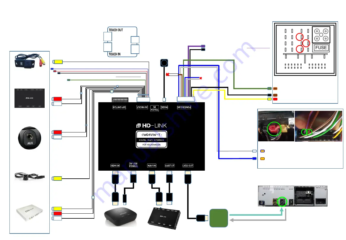
RV-CAM Video Input
IR OUT
External Rear View
Camera
Audio(AUX) Output of
Navigation Box
Auxiliary(AUX)
Input of the car
External Front View
Camera
AV device
(ex: DTV Box, Divx)
Navigation Box
DIP S/W Setting
LVDS
IN / OUT
PCB
Mode
Switch
(optional)
HDMI Device
HDMI
H
D
MI
HDMI
HDMI
USB
FV-CAM Video Input
(AV1)
12V Power Output
& GND Output(RV-CAM Power)
NAVI Audio Input
Audio Output
※
Optional External Devices
AV-Input(AV2)
Reverse Signal Detection(optional)
Full Installation Diagram
LVDS IN / OUT Connection
Head Unit(OEM)
6
HDMI
HDMI
USB
USB
AUDI MMI(Green
)
Pin # 10 = MMI DATA(Orange/Brown)
MMI DATA Pin Specification
Head Unit Original Main-Harness
1
4
5
8
9
10
12
13
15
16
Pin # 2 = CAN HIGH (Orange/Blue)
Pin # 3 = CAN LOW (Orange/Brown)
1 2 3
IR OUT
Pin # 12 = GND (Brown)
Pin # 15 = B+ POWER(Red)
TOUCH
BOARD
Touch board
Installation Diagram
Please refer to next page
NAVI 12V Power Output (For Navigation)
GND Output
LS CAN wires
(Some vehicles should be connected the
‘LS CAN wires'.)
Power / CAN
Cable
HS CAN H(White)
HS CAN L(Blue)
* 20-Pin Connector of Climate controller
Car-Solutions.com
www.car-solutions.com


