Car-Interface v.LOGiC CI-V5-CCC-PNP Manual Download Page 8


Version 05.02.2018


CI-V5-CCC-PNP


P

age


Connect female 8 pin molex connector of the harness TV-BM01 to the  
male 8 pin molex connector of the harness TV-BM01. 
 
 
Connect female 12pin AMP connector of the harness TV-BM01 to the  
front site of the V5C-M631 interface box. 


3.2.


LVDS connection 


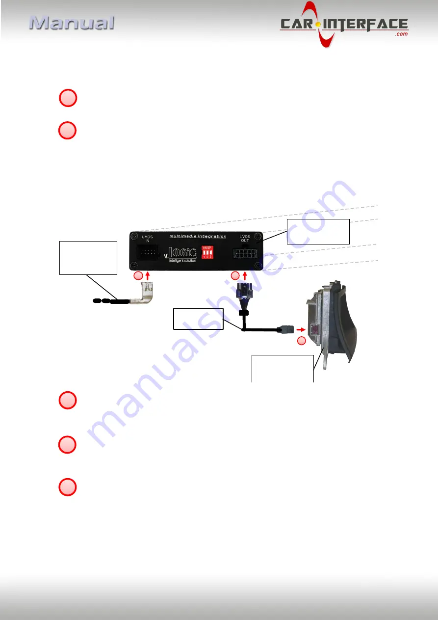
Connect the female 10pin Micro-Fit connector of the LVDS cable V4C-LVDS10 to the  
male 10pin Micro-Fit connector (LVDS-OUT) on the rear of the interface-box  
V5C-M631. 
 
Remove the female 10pin BMW LVDS connector of the vehicle harness at the side of  
the factory monitor and connect it to the male 10pin BMW LVDS connector (LVDS-IN)  
on the front of the interface-box V5C-M631. 
 
Connect the female 10pin BMW LVDS connector of the LVDS cable V4C-LVDS10 to  
the male 10pin BMW LVDS connector of the factory monitor. 


5


6


1


2


3


1

3

2

Interface-box

V5C-M631

REAR

10pin BMW

LVDS female

vehicle harness

Side view of the

factory monitor

LVDS cable

V4C-LVDS10

Summary of Contents for v.LOGiC CI-V5-CCC-PNP

Page 1: ...l operation modes Front camera input Manual switching to rear view camera only for vehicles with PDC button Manual return from rear view and front camera cancellation of automatic switching 2 trigger...

Page 2: ...market front camera 3 2 1 2 Settings for connecting an after market front camera 3 2 2 After market rear view camera 3 2 2 1 Connection to the after market rear view camera 3 2 2 2 Settings for connec...

Page 3: ...product This product should only be used while standing or to display fixed menus or rear view camera video when the vehicle is moving for example the MP3 menu for DVD upgrades Changes updates of the...

Page 4: ...heat sources 1 1 Delivery contents 1 2 Check compatibility of vehicle and accessories Requirements Navigation E series and Mini with navigation system or radio with 6 5 or 8 8 monitor with 10pin BMW...

Page 5: ...to set the monitor type The default setting is Vehicle navigation Dip 1 Dip 2 Dip 3 M ASK version 1 OFF OFF OFF M ASK version 2 OFF ON OFF CCC version 1 ON OFF OFF CCC version 2 ON OFF ON After each...

Page 6: ...Version 05 02 2018 CI V5 CCC PNP Page 5 2 Connection schema...

Page 7: ...e and device installation we suggest to connect and test correct function of all after market and factory infotainment equipment The interface is installed on the backside of the head unit 3 1 Connect...

Page 8: ...the male 10pin Micro Fit connector LVDS OUT on the rear of the interface box V5C M631 Remove the female 10pin BMW LVDS connector of the vehicle harness at the side of the factory monitor and connect i...

Page 9: ...T CAM of the interface box V5C M631 The pink wire of harness V5C UNI01 can be used for 12V electric power supply max 1A of the after market front camera Configure in the OSD menu MISC menu item POWER...

Page 10: ...Logic Intelligent For vehicles with PDC button Enabled while parking process and up to 20 km h or together with PDC if existing Gear only For vehicles without PDC button Enabled while parking process...

Page 11: ...n be used for 12V electric power supply max 1A of the after market rear view camera Configure in the OSD menu MISC menu item POWER OUT 2 the designated electric power supply see chapter Configurable s...

Page 12: ...erse gear is enabled and it displays factory rear view camera and or PDC display ReverseLogic Intelligent For vehicles with PDC button Enabled while parking process and up to 20 km h or together with...

Page 13: ...can configure the both trigger outputs in the OSD menu MISC separately Operation of the OSD see chapter OSD Operation OSD menu Menu item Setting Explication MISC POWER OUT1 pink POWER OUT2 green CAN 1...

Page 14: ...Picture settings You can change the picture settings in the OSD menu IMAGE Operation of the OSD see chapter OSD Operation Brightness Contrast Saturation Hue Sharpness Note The picture settings will b...

Page 15: ...of the interface in the OSD on screen display 4 1 1 OSD Operation You can control the OSD by iDrive 4 1 1 1 1 and 2 button iDrive Note If the interface is selected as active video source then the OSD...

Page 16: ...nd MISC can be configured over and above the described settings in this manual Operation of the OSD see chapter OSD Operation OSD menu Menu item Setting Explication H POSITION 0 xxx Horizontal positio...

Page 17: ...Video in motion deactivated For the V5 CIC E PNP the video in motion function is permanently active without disturbing the navigation performance 4 3 Selecting the interface as current AV source Long...

Page 18: ...nts box only B x H x T 141 x 30 x 105 mm 6 Connections interface box Legal disclaimer Mentioned company and trademarks as well as product names codes are registered trademarks of their corresponding l...

Reviews: