Caple DOMINO C621 Installation And Operating Instruction Booklet Download Page 4

Page 4 

C621 C721 user manual.DOC 


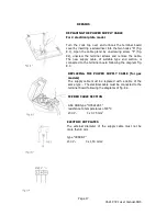
" 2 ELECTRIC" COOKING HOB (Fig. 1.3) 

Electrical insulation Class I. 
Overheating surfaces protection Type Y. 
1. Electrical plate Q) 145 - (1000 W - 1500 W) 
2. Electrical plate 0 180 - (1500 W - 2000 W) 
3. Electrical plate 1 control knob 
4. Electrical plate 2 control knob 
5. Power indicator light 


GAS BURNERS 

Gas  flow  to  the  burners  is  adjusted  by  turning  the  knobs 
(illustrated  in  fig.  2.1  b)  which  control  the  safety  valves. 
Turning  the  knob  so  that  the  indicator  line  points  to  the 

symbols printed on the panel achieves the following functions: 
 

Full circle 


closed valve 


Full circle 


maximum aperture or flow   


Full circle 


minimum aperture or flow. 


To light one of the gas burners, hold a flame (e.g. a match) close to 
the top part of the burner, push in and turn the relative knob in an 
anti-clockwise  direction,  pointing  the  knob  indicator  towards  the 

large flame symbol (i.e. max. gas flow). 
To  reduce  the  gas  flow  to  minimum,  rotate  the  knob  further 

anti-clockwise to point the indicator towards the small flame symbol. 
The  maximum  aperture  position  permits  rapid  boiling  of  liquids, 
whereas  the  minimum  aperture  position  allows  slower  warming  of 

food or maintaining boiling conditions of liquids. 

Other  intermediate  operating  adjustments  can  be  achieved  by  positioning  the  indicator 
between the maximum and minimum aperture positions, and never between the maximum 

aperture and closed positions. 
 

N.B.  When  the  cooker  top  is  not  being  used,  set  the  gas  knobs  to  their  closed 
positions and also close the cock valve on the gas bottle or the main gas supply 

line. 


PUSH BUTTON ELECTRIC SPARK-LIGHTING GAS 


To light one of the burners you have to push in and turn the relative knob to the maximum 
aperture  position  (large  flame  symbol)  and  press  the  electric  lighter  button  (fig.  2.2)  until 

the flame has been lit. 
 
Adjust the gas valve to the desired position. 

Summary of Contents for DOMINO C621

Page 1: ... HOBS C621 C721 INSTALLATION AND OPERATING INSTRUCTION BOOKLET IMPORTANT You must read this instruction Book before installing or using this appliance and retain it for future use Caple Products Telephone 0870 2411142 Facsimile 0117 982 6878 ...

Page 2: ...r or a professionally qualified technician Packing elements i e plastic bags polystyrene foam nails packing straps etc should not be left around within easy reach of children as these may cause serious injuries The packaging material is recyclable and is marked with the recycling symbol Do not attempt to modify the technical characteristics of the appliance as this may become dangerous to use The ...

Page 3: ... as heating a room is improper and dangerous This cooking hob has been designed constructed and marketed in compliance with Safety requirements of the Gas Directive 90 396 EEC Safety requirements of EEC Directive Low voltage 73 23 gas or gas electric appliances Safety requirements of EEC Directive EMC 89 336 gas or gas electric appliances Requirements of EEC Directive 93 68 FEATURES 2 GAS COOKING ...

Page 4: ... the knob indicator towards the large flame symbol i e max gas flow To reduce the gas flow to minimum rotate the knob further anti clockwise to point the indicator towards the small flame symbol The maximum aperture position permits rapid boiling of liquids whereas the minimum aperture position allows slower warming of food or maintaining boiling conditions of liquids Other intermediate operating ...

Page 5: ...ric hotplate rotate the knob fig 3 1 3 2 to the desired setting The numbers from 1 to 6 or 1 to 12 indicate the operating positions with increasing number corresponding to higher temperature settings When the pan comes to the boil turn the heat down to the level desired Remember that the hotplate will continue to produce heat for about five minutes after it has been turned off RAPID HOTPLATE red d...

Page 6: ...ible Never cook food directly on the hotplate always use a pan or suitable container An indicator light located close to the control panel signals that the hotplate is operating ELECTRIC HOTPLATE USAGE TABLE Position of switch TYPE OF COOKING 0 0 Switched OFF 1 2 1 2 For melting operations of butter or chocolate 2 2 3 4 To keep foods warm or heat small quantities of water 3 4 5 6 To heat greater q...

Page 7: ...GAS TAPS In the event of operating faults in the gas taps call the Service Department CLEANING ELECTRIC HOTPLATES Always clean when the hotplate is tepid Use a soft cloth dampened with water and a little salt To finish off use a soft cloth with a little oil Do not use water to avoid the formation of rust Do not use steam jet cleaners because the humidity could infiltrate into the appliance making ...

Page 8: ...been correctly positioned see figs 5 2 and 5 6 failure to do so can cause serious problems Check that the electrode S fig 5 2 is always clean to ensure trouble free sparking Check that the probe T fig 5 2 next to each burner is always clean to ensure correct operation of the safety valves Both the probe and ignition plug must be very carefully cleaned ...

Page 9: ...als e g curtains GAS HOBS TECHNICAL INFORMATION FOR THE INSTALLER Before installing the cook top remove the protective film This cook top can be built into a working surface 20 to 40 mm thick and 600 mm deep In order to install the cooker top into the kitchen fixture a hole with the dimensions shown in figs 6 1 a 6 1 b has to be made keeping in consideration the following Within the fixture betwee...

Page 10: ...into the unit and position it correctly Put tabs A into place and tighten screws B until the cook top is completely secured Using a sharp tool cut off the part of gasket C which protrudes from the cook top CHOOSING SUITABLE SURROUNDINGS for gas models The room where the gas appliance is to be installed must have a natural flow of air so that the gas can burn in compliance with the current laws in ...

Page 11: ...into kitchen fixtures measuring 600 mm in depth and from 20 to 40 mm thick for 2 electrical plates hob In order to install the cooker top into the kitchen fixture a hole with the dimensions shown in figs 6 8a and 6 8b has to be made keeping in consideration the following Within the fixture between the bottom side of the cooker top and the upper surface of any other appliance or internal shelf ther...

Page 12: ...Turn the tabs so that the cook top can be put into the hole Put the cook top into the hole cut into the unit and position it correctly Put tabs A into place tooth C of the tabs should go into the hole Tighten screws B until the cook top is completely secured Using a sharp tool cut off the part of gasket D which protrudes from the cook top GAS CONNECTIONS Make sure that the hob is adapted to functi...

Page 13: ...henever they are even slightly deformed or imperfect Any connection to fixed metal pipes must be done in such a way so as not to place undue stress on the hob chassis If using flexible metal pipes make sure they are not squashed and do not come into contact with moving parts Any flexible pipes must be so installed as to be easily inspected along their whole length They must be changed before the e...

Page 14: ...rs and the knobs Using a wrench substitute the nozzle injectors J Fig 7 3 7 4 with those most suitable for the kind of gas for which it is to be used The burners are made in such a way so as not to require the regulation of the primary air REGULATING THE BURNER MINIMUM SETTING When switching from one type of gas to another the minimum flow rate must also be cor rect the flame should not go out eve...

Page 15: ...mped on the appliance identification plate must be checked for correspondence to the available mains supply voltage and the mains electric wiring should be capable of handling the cooker s power rating also indicated on the identification plate The appliance is supplied without a power supply plug and therefore if you are not connecting directly to the mains a standardized plug suitable for the lo...

Page 16: ...the controls to position 1 for approximately 30 seconds to dry out any humidity This appliance must be connected by a competent person using fixed wiring via a DOUBLE POLE SWITCHED FUSED SPUR OUTLET We recommend that the appliance is connected by a qualified electrician who is a member of the N I C E I C and who will comply with the I E E and local regulations The wires in the mains lead are colou...

Page 17: ...pply cable of suitable type and section is connected to the terminal board following the diagram fig 8 3 REPLACING THE POWER SUPPLY CABLE for gas models The supply cable must be replaced with a cable of the same type The electrical cable must be connected to the terminal board following the diagrams of fig 8 4 FEEDER CABLE SECTION GAS HOB type H05V2V2 F resistance to temperatures of 90 C 230 V 3 x...

Page 18: ...te of purchase During that time should it become necessary CAPLE engineers will replace or repair all defective parts free of charge except for parts subject to fair wear and tear such as light bulbs Parts and the engineers labour costs are chargeable after the first 12 months To qualify for benefits under the guarantee you must be able to provide proof of date of purchase and the appliance must h...

Reviews: