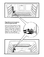
Fig. 3.4
M
J
A
Adjusting of primary air
of the top burners
By operating the screw “M”, reset the air
adjuster “A” according to the instructions
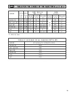
see “TABLE FOR THE CHOICE OF THE
INJECTORS”, where the distance
between injector and air adjuster is rec-
ommended (in mm).
Before lowering the hob top, set the
burners on their sites and light them in
order to check whether the flames are
correct, as per the specifications given in
the next page. In case of uncorrect
flame, lift or lower the air adjuster.
Injectors replacement of top burners
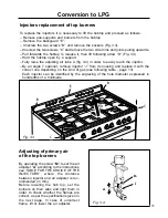
To replace the injectors it is necessary to lift the hobtop and proceed as follows:
– Remove pan-supports and burners from the hobtop.
– Remove the backguard “E”.
– Unscrew the two screws “B” and remove the sockets (Fig. 3.3).
– Unscrew the two screws “C” and remove the two side trims and joints pulling upwards.
– Pull forwards the hobtop to release it, then lift following arrow “D” (Fig. 3.3)
– Hold the hobtop open by a support.
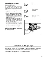
– Fully raise the adjusting air tube A (fig. 3.4) in order to easily reach the injector.
– By an angle 7 spanner, remove injector “J” from its housing and replace it with the
correct one depending on the kind of gas (see following table - page 13).
Each injector can be identified by the engraving of the hole diameter expressed in
hundredths of a millimetre.
Conversion to LPG
C
C
B
B
D
E
Fig. 3.3
11


