background image

9

3.2

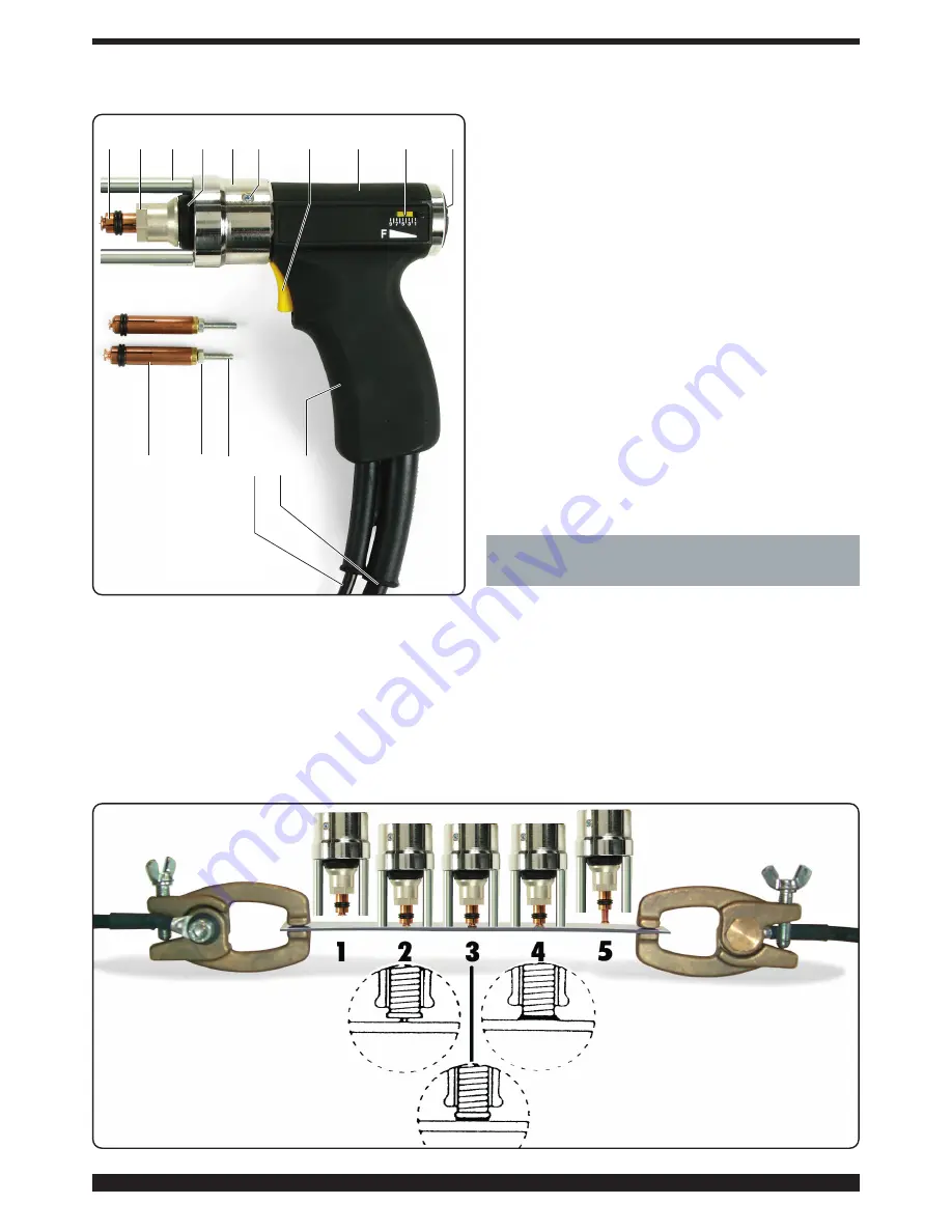
GUN DESCRIPTION

K-

Gun body

L-

Grip

M-

Control cable

N-

Welding current cable  

O-

Welding command button (works only with the gun
pressed against the sheet metal)

P-

Force setting indicator

Q-

Force adjustment screw (increases when turned clock

wise)

R-

Ring to hold spacer Z

S-

Clamp locking ring-nut

T

- Safety bellows

U-

Holding screws for ring R

V-

Screw to adjust stud bolt protrusion

W-

Holding nut.

X-

Stud bolt gripping clamp

Y-

Screw

Z-

Spacer

3.2.1 Preparing the gun

Always use high-quality pins with contact point start-up for
capacitor discharge welding, which comply with standards
and are made of a metal compatible with the welding to be
done.
Having selected the stud bolt to be welded for type, diame-
ter, length and material, use and adjust the clamp according
to the corresponding diameter.
Insert the stud bolt in the clamp 

X

so that it is firmly held in

place by the four springs.
Adjust the protrusion of the stud bolt from the front of the
clamp to 0.8 ÷ 1.2 mm using the screw 

V

, then tighten with the

nut 

W

(figure 2).

Insert the clamp 

X

into the chuck of the gun (fig. 2), press

until you feel it rest all the way down, and tighten the nut S
using the 17-mm hexagon wrench provided.

OPERATING PRINCIPLE OF WELDING 
THREADED STUD BOLTS WITH CONTACT 
POINT START-UP

(Fig. 3)

The stud bolt is inserted in the clamp X (phase 1), then posi-
tioned and pressed with its start-up contact directly against
the surface of the sheet metal to be welded (phase 2). The
spring of the gun presses the stud bolt against the metal, the
start command begins sending current which melts the
start-up contact, and the electrical arc is propagated along
the entire surface of the stud bolt (phase 4) pushed against
the metal surface. The molten metal solidifies, thereby weld-
ing the stud bolt (phase 5). 

X

X

W V M N L

S

Z

T

R U

O

K

P

Q

Fig. 2

Fig. 3

Summary of Contents for 3300828-F

Page 1: ...WEISSMASCHINE Seite 12 F MANUEL D INSTRUCTIONS POUR POSTE A SOUDER A DECHARGE DE CONDENSATEURS page 17 E MANUAL DE INSTRUCCIONES PARA SOLDADORA DE DESCARGA DE CONDENSADORES pag 22 20 03 13 3 300 828 F Pagg Seiten 27 31 Parti di ricambio e schema elettrico Spare parts and electrical schematic Ersatzteile und Schaltplan Pièces détachées et schéma électrique Partes de repuesto y esquema eléctrico ...

Page 2: ...ivi Maneggiare con cura le bombole ed i regolatori di pressione utilizzati nelle operazioni di saldatura COMPATIBILITÀ ELETTROMAGNETICA Questo apparecchio è costruito in conformità alle indicazio ni contenute nella norma armonizzata EN50199 e deve essere usato solo a scopo professionale in un ambiente industriale Vi possono essere infatti potenziali diffi coltà nell assicurare la compatibilità ele...

Page 3: ...cchina può funzionare per tensioni comprese tra 96V e 140V Se l alimentazione è 230V la macchina può funzionare per tensioni comprese tra 190V e 260V Il cambio di alimentazione deve essere eseguito a mac china spenta 3 3 Ai portatori di pace maker è proibito usare la macchina o avvicinarsi ai cavi 4 Inserire a fondo la spina del cavo di massa nella presa e ruotare in senso orario 5 Inserire a fond...

Page 4: ...ti alle norme e di metallo compatibile con le saldature da eseguire Scelto il prigioniero da saldare per tipo diametro lunghezza e materiale utilizzare e regolare la pinza in base al diametro corrispondente Inserire il prigioniero nella pinza X in modo che sia ben ser rato dalle quattro molle Regolare la sporgenza del prigioniero rispetto alla parte anteriore della pinza a 0 8 1 2 mm utilizzando l...

Page 5: ...ile effettuare alcune saldature di prova per determinare la corretta regola zione del generatore e la taratura della pistola forza della molla operando come segue inserire il prigioniero scelto nella pinza X preventivamente regolata come descritto in Fig 2 disporre la lamiera di base in condizioni identiche a quelle che saranno le condizioni di lavoro come spessore area dei Acciaio 0 2 C Inox Otto...

Page 6: ...ntervento del Attendere alcuni termostato minuti E 2 SCR in corto Contattare circuito l assistenza E 2 Connettore non Inserire il inserito correttamente connettore E 3 Tensione irregolare Contattare ai capi dei condensatori l assistenza E 4 Carica dei Contattare condensatori irregolare l assistenza E 5 Scarica dei Contattare condensatori irregolare l assistenza Prima di aprire la saldatrice attend...

Page 7: ...re regulators used in welding operations should be handled with care ELECTROMAGNETIC COMPATIBILITY This machine is manufactured in compliance with the instructions contained in the harmonized standard EN50199 and must be used solely for professional pur poses in an industrial environment There may be poten tial difficulties in ensuring electromagnetic compatibility in non industrial environments I...

Page 8: ...f the power supply is 230V the machine may run for voltages between 190V and 260V The machine must be switched off when changing the power supply 3 Pacemaker wearers are prohibited from using the machine or approach the cables 4 Fully insert the earth cable plug into the socket and turn clockwise 5 Fully insert the gun plug into the socket and turn clock wise 6 Turn on the welding machine using th...

Page 9: ...tud bolt in the clamp X so that it is firmly held in place by the four springs Adjust the protrusion of the stud bolt from the front of the clamp to 0 8 1 2 mm using the screw V then tighten with the nut W figure 2 Insert the clamp X into the chuck of the gun fig 2 press until you feel it rest all the way down and tighten the nut S using the 17 mm hexagon wrench provided 4 OPERATING PRINCIPLE OF W...

Page 10: ...d in Fig 2 arrange the base sheet metal in conditions identical to those that will be used for the job in terms of thickness earth connection area size of the workpiece material quality the terminals of the earth cable should be placed symmet rically and as close as possible to the welding point activate the power source by means of the lighted switch I grip the gun and press it against the sheet ...

Page 11: ...onnectors not Insert the inserted correctly connector E 3 Irregular voltage Contact technical at the capacitor tips lservice E 4 Irregular Contact technical capacitor charging lservice E 5 Irregular Contact technical capacitor discharging service Wait at least 5 minutes after shutting off the switch I before opening the welding machine and unplug the plug from the power socket Use a volt meter to ...

Page 12: ...in die Nähe von Lichtbogenschweiß Schneid Brennputz oder Punktschweißprozessen bege ben EXPLOSIONSGEFAHR Keine Schneid Schweißarbeiten in der Nähe von Druckbehältern oder in Umgebungen ausführen die explosiven Staub Gas oder Dämpfe enthalten Die für den Schweiß Schneiprozeß verwendeten Gasflaschen und Druckregler sorgsam behandeln ELEKTROMAGNETISCHE VERTRÄGLICHKEIT Dieses Gerät wurde in Übereinsti...

Page 13: ...den Schutzkontakt ange schlossen ist Der Nennstrom des in Reihe mit der Netzstromversorgung geschalteten Leistungsschutz Schalters oder der Schmelzsicherungen muss gleich dem von der Maschine aufgenommenen Strom I1 sein Ggf verwendete Verlängerungen müssen einen der Stromaufnahme I1 angemessenen Querschnitt haben Bei Eingangsspannung 115V ist der Betrieb der Maschine mit einer Spannung zwischen 96...

Page 14: ...uf das Blech gedrückt wird P Zeiger der Krafteinstellung Q Stellschraube für die Krafteinstellung zum Erhöhen nach rechts drehen R Abstandhalterring Z S Spannzangenblockierring T Schutzbalg U Feststellschraube für Ring R V Stellschraube für die Einstellung des Überstands des Bolzens W Feststellmutter X Spannzange zum Einspannen des Bolzens Y Schraube Z Abstandhalter 3 2 1 Vorbereitung der Schweißp...

Page 15: ... Edelstahl Aluminium und Messing geschweißt werden Dank der Schnelligkeit des Prozesses werden die Oberflächen auf der der Schweißung entgegengesetzten Seite nicht beeinträchtigt Nicht geschweißt werden können gehärteter Stahl und oxidierte oder lackierte Metalle Vor Aufnahme der Produktion muss man unbedingt einige Schweißproben durchführen um die richtige Einstellung der Stromquelle und der Schw...

Page 16: ...nsprechen des Einige Minuten Thermostaten abwarten E 2 Kurzschluss beim Kundendienst Siliziumthyristor kontaktieren E 2 Steckverbinder nicht Steckverbinder richtig eingesteckt einstecken E 3 Unregelmäßige Kundendienst Spannung an den kontaktieren Kondensatoranschlüssen E 4 Unregelmäßige Ladung Kundendienst der Kondensatoren kontaktieren E 5 Unregelmäßige Entladung Kundendienst der Kondensatoren ko...

Page 17: ...ières gaz ou vapeurs explosifs Manier avec soin les bouteilles et les déten deurs de pression utilisés dans les opérations de soudure COMPATIBILITE ELECTROMAGNETIQUE Cette machine est construite en conformité aux indications contenues dans la norme harmonisée EN50199 et ne doit être utilisée que pour des buts professionnels dans un milieu industriel En fait il peut y avoir des difficultés potentie...

Page 18: ...V la machine peut fonction ner pour tensions comprises entre 96V et 140V Si l alimentation est en 230V la machine peut fonction ner pour tensions comprises entre 190V et 260V La sélection de l alimentation doit être opérée avec la machine arrêtée 3 Aux porteurs de stimulateurs cardiaques il est défendu d utiliser la machine ou de s approcher des câbles 4 Enfoncer la fiche du câble de masse dans la...

Page 19: ...es goujons avec pointe d amorçage pour soudure par décharge de condensateurs de haute qualité conformes aux normes et de métal compatible avec les sou dures à exécuter Après avoir choisi le goujon à souder pour ce qui est du type diamètre longueur et matière utiliser et régler la pince selon le diamètre correspondant Insérer le goujon dans la pince X de façon à ce qu il soit bien serré par les qua...

Page 20: ...mmencer la production il est indispensable d ef fectuer quelques soudures d essai pour déterminer le cor rect réglage du générateur et l étalonnage du pistolet force du ressort en exécutant les opérations suivantes insérer le goujon choisi dans la pince X réglée au préalable comme décrit dans la Fig 2 ranger la tôle de base dans des conditions identiques aux futures conditions de travail pour ce q...

Page 21: ...ode Anomalie Remède erreur E 1 Entrée en service Attendre quelques du thermostat minutes E 2 SCR en Contacter court circuit l assistance technique E 2 Connecteur non Insérer le inséré correctement connecteur E 3 Tension irrégulière aux Contacter extrémités des l assistance technique condensateurs E 4 Charge des Contacter condensateurs irrégulière l assistance technique E 5 Décharge des Contacter c...

Page 22: ...vos Manejar con cuidado las bombonas y los regulado res de presión utilizados en las operaciones de soldadura COMPATIBILIDAD ELECTROMAGNÉTICA Este aparato se ha construido de conformidad a las indica ciones contenidas en la norma armonizada EN50199 y se deberá usar solo de forma profesional en un ambiente industrial En efecto podrían presentarse potenciales dificultades en el asegurar la compatibi...

Page 23: ...hibido usar la máquina o acercarse a los cables 4 Insertar a fondo la clavija del cable de masa en el enchu fe y girar en el sentido de las agujas del reloj 5 Insertar a fondo la clavija de la pistola en el enchufe y girar en el sentido de las agujas del reloj 6 Encender la soldadora con el interruptor I el encendido y el apagado no se repetirán con frecuencia la disipación de la energía contenida...

Page 24: ... bien apretado por los cuatro muelles Regular el saliente del espárrago respecto a la parte anterior de la pinza a 0 8 1 2 mm utilizando el tornillo V a continua ción bloquear con la tuerca W figura 2 Insertar la pinza X en el mandril de la pistola fig 2 presio narla hasta sentir que se apoya en el fondo y bloquear la tuerca S con la llave hexagonal 17 mm en dotación 4 PRINCIPIO DE FUNCIONAMIENTO ...

Page 25: ...nsertar el espárrago elegido en la pinza X previamente regulada como se describe en la Fig 2 disponer la chapa de base en condiciones idénticas a lo que serán las condiciones de trabajo como espesor área de las conexiones de masa dimensiones de la pieza calidad del material Los bornes del cable de masa se colocarán de forma simé trica y los más cerca posible al punto de soldadura activar el genera...

Page 26: ... ntervención Esperar algunos del termostato minutos E 2 SCR en Contactar corto circuito la asistencia E 2 Conectores no Insertar el insertados correctamente conector E 3 Tensión irregular en Contactar los extremos de los la asistencia condensadores E 4 Carga de los Contactar condensadores irregulares la asistencia E 5 Descarga de los Contactar condensadores irregulares la asistencia Antes de abrir...

Page 27: ... UITSLUITEND BESTEMD VOOR BEVOEGD PERSONEEL DENNA DEL ÄR ENDAST AVSEDD FÖR KVALIFICERAD PERSONAL AUTOV TO TMHVMA PROORIVZETAI APOKLEISTIKAV GIA TO EIDIKEUMEVNO PROSWPIKO V CODIFICA COLORI WIRING DIAGRAM CABLAGGIO ELETTRICO COLOUR CODE A NERO BLACK B ROSSO RED C GRIGIO GREY D BIANCO WHITE E VERDE GREEN F VIOLA PURPLE G GIALLO YELLOW H BLU BLUE K MARRONE BROWN J ARANCIO ORANGE I ROSA PINK CODIFICA C...

Page 28: ...28 ...

Page 29: ...29 ...

Page 30: ...INSULATION 34 VENTOLA FAN 35 SUPPORTO VENTOLA FAN SUPPORT 36 PROTEZIONE PROTECTION 37 PANNELLO ANTERIORE FRONT PANEL 38 CONNETTORE CONNECTOR 39 CORNICE FRAME 40 SUPPORTO MANICO HANDLE SUPPORT 41A SCR Ø 42 SCR Ø 42 41B SCR Ø 50 SCR Ø 50 When ordering spare parts please always state the machine item and serial number and its purchase data the spare part position and the quantity La richiesta di pezz...

Page 31: ...AGONALE 3 ALLEN WRENCH 3 123 PROVA PERNI RIVET TESTER 124 CHIAVE ESAGONALE WRENCH 125 PINZA P PERNI 3 PZ 1xTIPO MANDREL 3 PCS 1 FOR TYPE 126 DISTANZIALI 3 PZ SPACER 3 PCS 127 CHIAVE A TUBO PIPE WRENCH 128 SPUGNA ABRASIVA ABRASIVE SPONGE 130 KIT ACCESSORI COMPLETO ACCESSORIES KIT 130 ...

Page 32: ...32 ...

Reviews: