background image

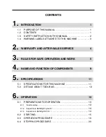
7.

MAINTENANCE

25

7.1

REGULAR INSPECTION CHART . . . . . . . . . . . . . . . . . . . . . . . . . . . . . . . . . 25

7.2

OIL/GREASE/LUBRICANT/FLUID LIST . . . . . . . . . . . . . . . . . . . . . . . . . . 28

7.3

CONSUMABLES (SERVICE PARTS) LIST . . . . . . . . . . . . . . . . . . . . . . . 29

7.4

LUBRICATION  . . . . . . . . . . . . . . . . . . . . . . . . . . . . . . . . . . . . . . . . . . . . . . . . . . . . . . 30

7.4.1

Engine Oil

. . . . . . . . . . . . . . . . . . . . . . . . . . . . . . . . . . . . . . . . . . . . . . . . . . . . . . . . . . . 30

7.4.2

Transmission Oil

. . . . . . . . . . . . . . . . . . . . . . . . . . . . . . . . . . . . . . . . . . . . . . . . . . . . . . 31

7.4.3

HST Oil

. . . . . . . . . . . . . . . . . . . . . . . . . . . . . . . . . . . . . . . . . . . . . . . . . . . . . . . . . . . . . . 32

7.5

LUBRICATION AND GREASING . . . . . . . . . . . . . . . . . . . . . . . . . . . . . . . . . . 33

7.5.1

Lubrication

. . . . . . . . . . . . . . . . . . . . . . . . . . . . . . . . . . . . . . . . . . . . . . . . . . . . . . . . . . . 33

7.5.2

Greasing

. . . . . . . . . . . . . . . . . . . . . . . . . . . . . . . . . . . . . . . . . . . . . . . . . . . . . . . . . . . . 34

7.6

POURING BATTERY FLUID  . . . . . . . . . . . . . . . . . . . . . . . . . . . . . . . . . . . . . . . 35

7.6.1

Battery Fluid

. . . . . . . . . . . . . . . . . . . . . . . . . . . . . . . . . . . . . . . . . . . . . . . . . . . . . . . . . 35

7.7

CLEANING  . . . . . . . . . . . . . . . . . . . . . . . . . . . . . . . . . . . . . . . . . . . . . . . . . . . . . . . . . . 37

7.7.1

Air Cleaner Element

. . . . . . . . . . . . . . . . . . . . . . . . . . . . . . . . . . . . . . . . . . . . . . . . . . . 37

7.7.2

Spark Plug

. . . . . . . . . . . . . . . . . . . . . . . . . . . . . . . . . . . . . . . . . . . . . . . . . . . . . . . . . . . 38

7.7.3

Fuel Cock (Fuel Filter)

. . . . . . . . . . . . . . . . . . . . . . . . . . . . . . . . . . . . . . . . . . . . . . . . . 39

7.7.4

Blower Housing and Cooling Fan

. . . . . . . . . . . . . . . . . . . . . . . . . . . . . . . . . . . . . . . 40

7.8

ADJUSTMENT  . . . . . . . . . . . . . . . . . . . . . . . . . . . . . . . . . . . . . . . . . . . . . . . . . . . . . . 41

7.8.1

V Belt for Driving

. . . . . . . . . . . . . . . . . . . . . . . . . . . . . . . . . . . . . . . . . . . . . . . . . . . . . 41

7.8.2

Blade Rotary V Belt

. . . . . . . . . . . . . . . . . . . . . . . . . . . . . . . . . . . . . . . . . . . . . . . . . . . 41

7.8.3

Rotary Stopper

. . . . . . . . . . . . . . . . . . . . . . . . . . . . . . . . . . . . . . . . . . . . . . . . . . . . . . . 41

7.8.4

Brake Pedal

. . . . . . . . . . . . . . . . . . . . . . . . . . . . . . . . . . . . . . . . . . . . . . . . . . . . . . . . . . 42

7.8.5

HST Lever

. . . . . . . . . . . . . . . . . . . . . . . . . . . . . . . . . . . . . . . . . . . . . . . . . . . . . . . . . . . 42

7.8.6

Tire Pressure

. . . . . . . . . . . . . . . . . . . . . . . . . . . . . . . . . . . . . . . . . . . . . . . . . . . . . . . . 42

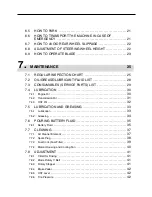
6.5

HOW TO PARK  . . . . . . . . . . . . . . . . . . . . . . . . . . . . . . . . . . . . . . . . . . . . . . . . . . . . . 21

6.6

HOW TO TRANSPORT THE MACHINE IN CASE OF 
EMERGENCY . . . . . . . . . . . . . . . . . . . . . . . . . . . . . . . . . . . . . . . . . . . . . . . . . . . . . . . 21

6.7

HOW TO AVOID REAR WHEEL SLIPPAGE . . . . . . . . . . . . . . . . . . . . . . 22

6.8

ADJUSTMENT OF STEERING WHEEL HEIGHT . . . . . . . . . . . . . . . . 22

6.9

HOW TO OPERATE BLADE  . . . . . . . . . . . . . . . . . . . . . . . . . . . . . . . . . . . . . . . 23

Summary of Contents for CM1801

Page 1: ...Fax 0943 75 4396 Read and understand this manual completely before attempting to operate maintain and inspect this machine Keep this manual with care so that it may be consulted in oper ating maintain...

Page 2: ...ons in this manual when oper ating maintaining or inspecting the machine WARNING This machine is a work vehicle for mowing Do not use it for other purposes Driving this machine on a public road or its...

Page 3: ...CE 4 3 RULES FOR SAFE OPERATION AND WORK 5 4 NAME AND FUNCTION OF COMPONENTS 9 5 SPECIFICATIONS 11 5 1 SPECIFICATIONS FOR THIS MACHINE 11 5 2 DETAILS ABOUT TOOL BAG 12 6 OPERATION 13 6 1 PREPARATIONS...

Page 4: ...7 6 1 Battery Fluid 35 7 7 CLEANING 37 7 7 1 Air Cleaner Element 37 7 7 2 Spark Plug 38 7 7 3 Fuel Cock Fuel Filter 39 7 7 4 Blower Housing and Cooling Fan 40 7 8 ADJUSTMENT 41 7 8 1 V Belt for Drivin...

Page 5: ...hine Appendix Instruction manual for engine Included in the tool bag Be sure to read it together with this manual 8 STORAGE LONG TERM 45 8 1 VEHICLE BODY 45 8 2 BATTERY 46 8 3 ENGINE 46 8 3 1 Fuel Coc...

Page 6: ...describes the general safety rules which the user must observe when operating and working 4 NAME AND FUNCTION OF COMPONENTS This chapter explains the names and functions of the component parts 5 SPECI...

Page 7: ...an extremely hazardous situation which will result in death or serious injury if the user does not follow appropriate instructions Indicates a potentially hazardous situation which could result in dea...

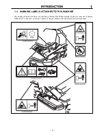
Page 8: ...LS ATTACHED TO THIS MACHINE The warning labels shown below are attached to this machine When warning labels have come off or become difficult to see order new ones from a dealer by the part numbers sh...

Page 9: ...he product model and product s serial number shown in the model label as well as the names of the manu facturer and model of the engine installed For the names of the manufacturer and model of the eng...

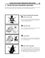
Page 10: ...n charging the bat tery or servicing the engine NEVER CARRY PASSENGERS The seating capacity of this machine is only one for the oper ator It is extremely dangerous to drive this machine with a fellow...

Page 11: ...ED Drive at safe speeds on a slope in accordance with the condi tions ENGINE BRAKE ON DOWN HILL When driving down a slope stop once before going down and set the aux speed change lever to the Low posi...

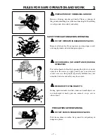
Page 12: ...children may not enter the work area and safety may be ensured BEWARE OF FLYING OBJECTS During operation make sure that stones and small objects are not discharged to nearby persons animals crops car...

Page 13: ...the mower while the engjne is running Always do service work after stopping engine PRECAUTIONS FOR VENTILATION When operating the engine indoors make sure that there is enough ventilation to prevent p...

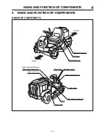
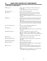
Page 14: ...CTION OF COMPONENTS 9 Differential lock lever HST lever Accelerator lever Blade height adjusting lever Blade height adjustment Blade clutch lever Parking brake lock lever Brake pedal AUX speed change...

Page 15: ...this lever when shifting speed to high low levels Speed shift can be used while driving Brake pedal Use to stop the machine When depressing brake pedal HST lever returns to neutral and stops the mach...

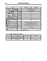
Page 16: ...Rear 735 MINIMUM FREEBOARD mm 105 M O D E L GH400V GM400PV FH531V T Y P E Air cooled 4 cycle gasoline Air cooled 4 cycle gasoline V twin C Y L I N D E R mm 84 70 68 68 B O R E X S T RO K E TOTAL DISPL...

Page 17: ...S T E E R I N G D E V I C E Rack and pinion type round steering wheel B R A K E T Y P E Internal expanding type brake T I R E Front AGR3 50 7 Rear 16 7 00 8 CUTTER BLADE WIDTH mm 900 CUTTER BLADE HEIG...

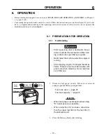
Page 18: ...8 Fuel tank capacity page 28 When fuel gauge needle approaches empty E refuel as soon as possible When using the unit on slopes refuel less than the upper fuel limit for the fuel filter in the lubrica...

Page 19: ...ompleted completely tighten the oil gauge with reliability N O T E 6 1 3 Inspection of the amount of HST oil and replenishment 1 Remove the screw for the oil checking port of the HST oil tank and chec...

Page 20: ...tion 4 Blade height adjusting lever should be in TRAVEL posi tion When the clutch of blade clutch lever is in ON position a safety switch is engaged and engine will not start N O T E 15 6 OPERATION 2...

Page 21: ...peed Engine control lever Engine control lever 8 Adjust the accelerator lever in the neutral position between High speed and Low speed In the case of CM 1305 7 Move the accelerator lever to the High s...

Page 22: ...Quick restarting may damage the starter gear When the operator does not sit on the seat a safety switch is engaged and engine will not start During engine operation never turn the key to START positi...

Page 23: ...ad and avoid severe operations In some areas where temperature is very low oil viscosity increases and normal oper ation may not be possible Continue warm ing up engine as indicated in the following c...

Page 24: ...to the rear WHEN CHANGING SPEEDS 6 When conditions require speed changes put the aux speed change lever to High or Low position Speed shift is available when travelling 19 6 OPERATION 6 3 OPERATION PR...

Page 25: ...the key Never leave the key in the ON position with the engine This may cause discharging of the battery because a current from the battery con tinues to flow to each circuit N O T E 6 Depress the bra...

Page 26: ...ition 4 Move the blade height adjusting lever to the Transport position 6 6 HOW TO TRANSPORT THE MACHINE IN CASE OF EMERGENCY If the base unit does not operate with normal control due to engine failur...

Page 27: ...ERING WHEEL HEIGHT 1 Release the adjusting knob and adjust the height of steering handle by moving up or down 2 Tighten the knob after adjusting height 22 OPERATION 6 7 HOW TO AVOID REAR WHEEL SLIPPAG...

Page 28: ...lose to each cover during operation When using machine for the first time select flat ground and operate slowly so that each cutting paths overlaps When cutting around obstacles always position trees...

Page 29: ...side of the grass outlet cover Beware of stones or other objects which may come of cutter blade area when opening the grass outlet cover Therefore ensure the safety completely Carry out the mowing op...

Page 30: ...for axle lever drag engine stall and knocking After warming up engine run engine from idling to high speed and check exhaust gas color and noise Check for gas leak from muffler exhaust pipe etc Check...

Page 31: ...Check oil amount in case Check oil for contamination Check case for oil leak Check if the lever fits into each speed position and moves smoothly when driving Check connection for looseness or rattle C...

Page 32: ...s for damage and looseness at connection Repeatedly operate brake and check connection for looseness and missing split pins Check body and cover for crack deformation and loose missing bolt nut Operat...

Page 33: ...hours 2nd or later every 500 operating hours Every six months No need for lubrication for the first 6 months after purchase Every six months No need for greasing for the first 6 months after purchase...

Page 34: ...53080325000 53090105000 53040209000 53090106000 53062431000 36103014000 36083229000 53064311000 53044205000 53044202000 53044203000 53044204000 53044204100 A3600101202 A3110101203 05200132025 53064301...

Page 35: ...eplace it Fuel to be used page 28 Amount of engine oil In the case of CM1801 Within the range A with the oil gauge tight ened In the case of CM1305 Between the upper and lower limits of the oil gauge...

Page 36: ...bolthole Amount of oil page 28 Up to a point where oil reaches the oil level check bolthole To add oil 1 Remove lubricating plug 2 Pour the designated oil from the lubrication port Oil to be used pag...

Page 37: ...and drain oil Properly dispose of drained oil 3 Replace the drain plug 4 Open the refueling cap and put in a proper amount of designated oil N O T E 32 MAINTENANCE Replacement 1 Prepare an appropriat...

Page 38: ...ed page 28 1 King pin Pin for front axle shaft 2 Brake link section 3 Fulcrum of rotary stopper 33 MAINTENANCE 7 5 LUBRICATION AND GREASING Insufficient or improper greasing can cause seizure or rust...

Page 39: ...f aux speed change lever 5 Blade clutch lever fulcrum 6 7 Fulcrum of cutter height adjusting lever link 8 Brake arm fulcrum 9 HST lever fulcrum 10 Brake pedal fulcrum 11 12 13 14 Blade stay fulcrum 11...

Page 40: ...level Between upper and lower reference lines Battery fluid Distilled water Charging Always remove the battery from the vehicle before charging Charging the battery on vehicle may cause damage to elec...

Page 41: ...used only in emergencies After quick charging always fully recharge the battery according to the proper procedure as soon as possible Quick charging will extremely shorten battery life N O T E 1 Remov...

Page 42: ...ement and paper element Then install them on the main body with the wing bolt If the air cleaner is noticeably dirty or damaged replace it 4 Install the cover on the main body N O T E Replacing Inspec...

Page 43: ...airpressure 2 1 kg cm2 or less to blow from the inside of the element or shaking the element slightly by hand Never allow the air cleaner to contain oil When the air cleaner is very dirty or damaged r...

Page 44: ...ck is closed N O T E 2 Remove filter pot oil seal and fuel filter 3 Remove deposits dust or water etc inside of filter pot 39 7 MAINTENANCE 2 Remove the spark plug using a plug wrench 3 Check the plug...

Page 45: ...lts 4 pcs for fuel tank 4 Move fuel tank to forward position and fix it 5 Remove blower housing fixing bolts and detach the shroud 6 Inspect cooling fins for dirt or dust Clean with com pressed air CA...

Page 46: ...lt with 3 to 5 mm when belt slips out of rotary check the clearance on belt holder at rotary side 41 7 MAINTENANCE 7 8 ADJUSTMENT 7 8 1 V Belt for Driving Inspection 1 Visually check for damage on V b...

Page 47: ...to Neutral while driving Remove seat move tension bolt at the foot of HST lever in direction of arrow and adjust the lever movement 42 7 MAINTENANCE 7 8 4 Brake Pedal If brake pedal play increases imm...

Page 48: ...e grade and viscosity 4 When checking oil level insert the oil gauge completely before removing again and confirming the level 5 Start engine and check for oil leakage 7 9 3 HST Oil filter CM1801 Repl...

Page 49: ...e stay hole C with the cutter blade hole D Because the cup square neck bolt wears out be sure to check it for wear When it is badly worn away replace it 3 Insert a high strength rod like thing such as...

Page 50: ...osition 6 Lubricate and grease areas to be lubricated and greased Pages 33 and 34 7 Remove key from the main switch 45 8 STORAGE LONG TERM 8 STORAGE LONG TERM When storing the vehicle for a long time...

Page 51: ...he engine N O T E 46 8 STORAGE LONG TERM 8 2 BATTERY 1 Remove the battery from the vehicle Page 35 When storing with battery in machine disconnect minus battery cable 2 Check the battery fluid level a...

Page 52: ...gine oil Pages 30 47 8 STORAGE LONG TERM 8 3 2 Cleaning Air Cleaner Element 1 Remove the air cleaner element and thoroughly clean it Pages 37 and 38 Air cleaner element CM1305 CM1801 Air cleaner Wing...

Page 53: ...position Safety device is actuated Brake pedal is not depressed Safety device is working Battery is over discharged Battery cable is disconnected Fuse is blow Open circuit or contact failure of wiring...

Page 54: ...nting bolts Others Engine oil leak Insufficient engine oil Blower housing and cooling fin clogging Fuel leak from fuel system Clogged air cleaner Choke not opened completely Poor compression Clogged a...

Page 55: ...um Water penetrates inside of drum Worn out tire Incorrect adjustment Incorrect tire air pressure Insufficient greasing for king pin Maifunction inside of steering gear Incorrect tie rod adjustment In...

Page 56: ...ed blade Corrective action Perform the operation after grass becomes dry Mow twice with a higher mowing height Set the mower to a higher mowing height Page 24 Set the mower to the maximum motor speed...

Page 57: ...f blade Low engine speed Operating speed too high Grass accumulating or coiling around blade or around shaft Corrective action Replace the blade with a new one or balance the blade properly Pages 43 a...

Page 58: ...curely hook the running boards to truck so that there is no difference in height between the boards and the truck s loading bed 10 TRANSPORTATION OF WITH THIS VEHICLE 53 Do not allow any one to come n...

Page 59: ...r 03 3552 6277 FAX 3552 6288 Tokyo Center 03 3552 6255 FAX 3552 6288 Sendai Center 022 281 1255 FAX 281 3141 Saitama Center 0495 77 4511 FAX 77 2949 Osaka Center 0790 42 6031 FAX 42 6035 Hiroshima Cen...

Reviews: