Jolly Rev.05 Ed. Sett.2010(I)
5/24
1.2. Description
The dump body is made up of the following units:
:
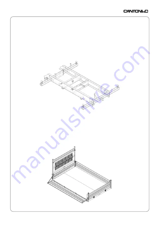
1.2.1
Subframe:
The subframe is composed of welded steel profiles; its function is to
reinforcethe chassis of the vehicle to which it is bolted. The
subframe accommodates the lifting gear and relative hydraulic
system.
1.2.2
Load body:
The body is composed of a load floor complete with side boards and
a tailgate of various different types in accordance with the specific
type of dump truck. The load-bearing frame is fabricated from
pressed steel profiles. The panels making up the load floor and the
sides are in different gauges and materials in relation to the specific
type of use for which the dump truck is designed.
Example of a subframe
for tripartite body
Example of a tripartite
body