5
5.MACHINE ADJUSTMENT
5-1 Work Table:
The work table is raised and lowered by two screws supported on
thrust bearings and is guided by machine surfaces on the side panels.
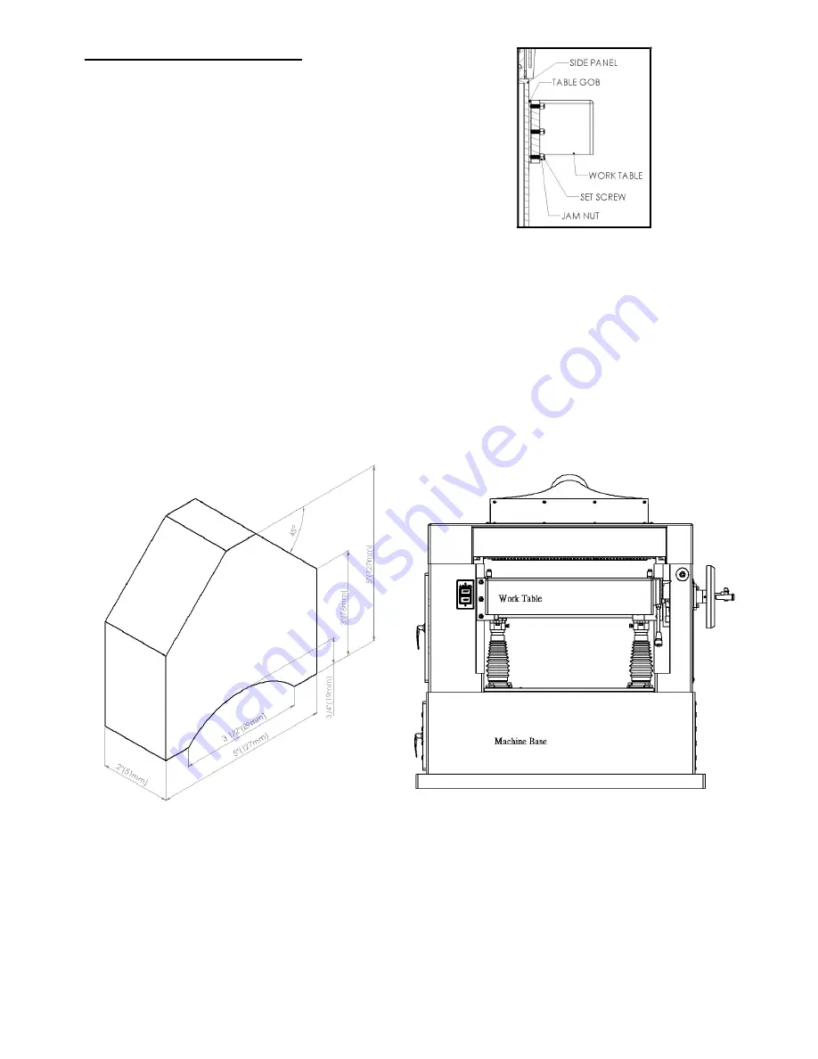
The fit-up to prevent the table form rocking is controlled by two
gibs in front. These gibs should be adjusted individually using the
set screws provided (Fig. 3) so that the ways are lightly contacting
on all four surfaces. The gibs should be tight enough to prevent
rocking of the table when the planer is in operation.
Fig. 3
To do accurate planing, the table must be parallel with the cutterhead. Lack of parallelism results in a taper over the width of a board. Check
with knife gage to insure knives have the same protrusion form the cutterhead arc end to end and that each knife is the same.
Place a 5" x5" (127mm x 127mm) gage block (Fig. 4) and shop scale to be used as a feeler gage or bed and table roll gage at the extreme
right hand side of the table, rotating head so the knives clear the gage surface. Raise the table with the table raising handwheel until the scale
on top of the block just touches the cutterhead. If using the indicator gage, establish the low point of the cutterhead are by moving the gage
front to back for the maximum indicator reading and then zero the dial at this point (Fig. 5). Move the block or indicator gage to the extreme
left side of the table. Using the indicator gage or block, find the low point of the cutterhead arc without moving the table height.
Fig. 4 Fig. 5


