background image


23 

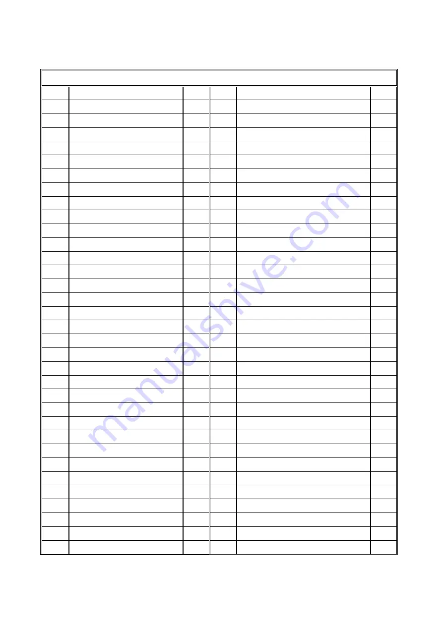
PART LIST 

303S    RIP SAW                                                                                                3/3 

NO 

PART NAME 

Q’TY 

NO 

PART NAME 

Q’TY 

501 

Slide seat press board 

534 

Bearing nut(left thread) 

502 

Block 

535 

Roller 

503 

Feeding roller seat 

536 

Side roller seat 

504 

Safety guard(outfeed) 

537 

Oil nozzle (straight) 

505 

Hinge 

538 

Roller seat (big) 

506 

Dust hood 

539 

Roller shaft (long) 

507 

Pin 

540 

Roller (big) 

508 

Spaced ring 

541 

Spring plate shaft seat 

509 

Connecting rod 

542 

Spring plate     

22 

510 

Guard plate 

543 

Spring plate (short) 

511 

Lobe knob 

544 

Spring plate shaft     

512 

Bearing 696 

545 

Spring plate buffer   

513 

Lifting nut 

546 

Steel ball 

514 

L handle 

547 

Spring 

515 

Index 

548 

Anti-kickback rocker arm 

516 

Pressure block 

549 

Anti-kickback rocker arm handle 

517 

Slide seat press board 


518 

Spring fixing nut 


519 

Spring (short) 


520 

Bearing fixing nut 


521 

Bearing 6204 


522 

Roller 


523 

Bearing nut 


524 

Rear roller seat 


525 

Roller shaft (long) 


526 

Oil nozzle 


527 

Spindle 


528 

Side roller seat 


529 

Spring (long) 


530 

Roller shaft (short) 


531 

Roller (small) 


532 

Bearing 6202 


533 

Bearing nut (right thread) 


Summary of Contents for 303S

Page 1: ...antekamerica com Please ensure you have your serial number available when contacting us for parts or service Cantek America Inc 1 888 982 2683 Parts sales cantekamerica com Service service cantekamerica com 303S SINGLE BLADE RIPSAW ...

Page 2: ...ourse the products which before to deliver to the endorsers our company has made the necessary testing measuring practical operations But it is essential to the machinery performance which is based on the accurate maintenance and operations Since we wish our honorable customers must practice operating method and maintenance regularly The manual is suggested to assist the user to understand the ope...

Page 3: ...STMENT 2 3 POWER WIRES CONNECTION 4 SOCKET FOR LASER 5 CONNECTING TO DUST COLLECTION SYSTEM 6 WOOD THICKNESS ADJUSTMENT 7 LIMIT SWITCH ON BLADE DOOR 8 SAWBLADE REPLACEMENT 9 SAWBLADE REPLACEMENT 10 AUTO PUMP OIL LEVEL 11 MAINTENANCE 12 WIRING DIAGRAM 1 13 WIRING DIAGRAM 2 14 DIAGRAM PART LIST 15 ...

Page 4: ...ental alertness is required at all times when running a machine 7 MAKE all adjustments with the power OFF 8 NEVER LEAVE TOOL RUNNING UNATTENDED TURN POWER OFF DO NOT leave tool until it comes to a complete stop 9 MAKE SURE wiring codes are recommended electrical connection instructions am followed and that the machine is property grounded 10 DISCONNECT machine from power source when make repairs 1...

Page 5: ... After locating the box loosen screws by tools and then turn the box to the operating position When all is done please lock and fix it Figure2 Figure 2 3 The correct operating position Figure 3 1 The location is for installing the control panel box Figure 1 ...

Page 6: ...3 CONTROL PANEL ADJUSTMENT 2 Correct Direction Figure 1 2 1 The front of control panel 2 The bottom of control panel ...

Page 7: ...NNECTION 1 Notice the sawblade direction when the power source is connected 2 If the direction is wrong simply change the R S wires R S T E Ground Wire Green color Yellow with green color Power Lines Correct Direction ...

Page 8: ...5 SOCKET FOR LASER There is a socket for a laser mounted on the electric cabinet s upper ...

Page 9: ...ne dust hood outlet for connecting to a dust collection system The dust hood outlet is located in the top of the machine The dust hood outlet is 5 in diameter Use a flexible hose with correct diameter to connect it to a dust collection system DUST HOOD OUTLET 5 DIAMETER ...

Page 10: ...ting the thickness of workpiece For example the thickness of workpiece is 30mm The number of scale should be 27mm and to press down 3mm for suppress the workpiece Refer to the following figure 1 2 a L HANDLE for adjusting the handwheel b HANDWHEEL Turn the wheel clockwise the wheel up Turn the wheel anticlockwise the wheel down Figure 1 Figure 2 ...

Page 11: ...blade door When the operator opens the blade door the machine s electric power is shut off immediately Please note Always shut off the power source and wait for the machine to completely stop running before doing any maintenance adjustments and changing the saw blade LIMIT SWITCH ...

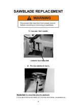
Page 12: ...PLACEMENT 1 Loosen the handle 2 The handwheel rises L Handel for loosen the sawblade Handwheel for rising lowering the sawblade Turn the wheel clockwise the sawblade up Turn the wheel anticlockwise the sawblade down ...

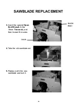
Page 13: ...10 SAWBLADE REPLACEMENT 3 Insert the special Open End Wrench the 19mm T wrench and then loosen the screw 4 Take the old sawblade out 5 Replace with the new sawblade and lock it Open End Wrench T wrench ...

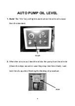
Page 14: ...m when the oil level is lower than the standard 2 When the oil runs out feed the oil into the pump from the oil inlet Clean the chips around in case they drop into the oil tank Last lock the oil cap when finishing the feeding oil procedure OIL light Oil Inlet ...

Page 15: ...12 MAINTENANCE 1 Refill grease into oil inlet on the saw spindle per 150 hours the spindle runs 2 Clean the Caterpillar after daily operation to keep its smooth and life span Caterpillar ...

Page 16: ...13 WIRING DIAGRAM 1 ...

Page 17: ...14 WIRING DIAGRAM 2 ...

Page 18: ...15 DIAGRAM PART LIST ...

Page 19: ...16 ...

Page 20: ...17 ...

Page 21: ...18 ...

Page 22: ...19 ...

Page 23: ... 237 Socket for laser 1 210 Rear door 1 211 Rear safety guard 1 212 Switch box 1 212 1 Panel 1 212 2 Emergency stop 1 212 3 Power lamp 1 212 4 Oil light 1 212 5 Feeding start 1 212 6 Feeding stop 1 212 7 Saw start 1 212 8 Saw stop 1 213 Switch box elbow 1 214 Right lower side door 1 215 Motor seat shaft 1 216 Cabinet 1 218 Chain cover 1 219 Brush long 2 219 1 Fixing Brush Shaft 1 220 Oil pump guar...

Page 24: ...305 Tooth bar fixing plate left 1 320 Slide block 50 306 Scale on tooth bar 1 321 Chain 1 307 Chain wheel shaft 1 322 Fence gear 1 308 Parallel key 1 323 Taper pin 1 309 Bearing 2 324 Handwheel 6 5 8 1 310 Chain wheel 1 325 Oil nozzle straight 1 311 Supporting plate 1 326 Lower anti kickback plate 14 312 Cabinet board 1 327 Lower anti kickback seat 1 313 Slide rail 1 328 Spring plate shaft 1 314 C...

Page 25: ...back finger bracket 1 413 Spindle sleeve 1 447 L handle M12 1 414 Fixing ring 1 448 Scale 1 415 Spindle sleeve shaft 1 449 Spring plate shaft 1 416 Wave gasket 1 450 Anti kickback supporting plate 1 417 Rear bearing fixing ring small 1 451 Bakelite Handle 1 418 Bearing 6306 1 452 Spring plate shaft seat left 1 419 Pulley adjusting bolt 1 453 Spring plate buffer 1 420 Spindle rear cover 1 454 Anti ...

Page 26: ...Guard plate 1 543 Spring plate short 2 511 Lobe knob 1 544 Spring plate shaft 1 512 Bearing 696 3 545 Spring plate buffer 1 513 Lifting nut 1 546 Steel ball 1 514 L handle 1 547 Spring 1 515 Index 1 548 Anti kickback rocker arm 1 516 Pressure block 1 549 Anti kickback rocker arm handle 1 517 Slide seat press board 1 518 Spring fixing nut 6 519 Spring short 2 520 Bearing fixing nut 2 521 Bearing 62...

Reviews: