background image

OM-1587 Page 21

SECTION 7 – SETTING DUAL SCHEDULE PARAMETERS
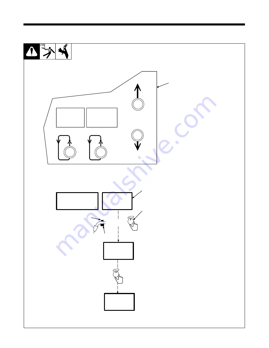
7-1.

Selecting Dual Schedule Pair

Dual Schedule is used with two
consecutive weld programs 1 & 2,
3 & 4, 5 & 6, or 7 & 8. Any program
type (MIG, Adaptive Pulse, or
Pulse) can be combined in dual
schedule.

1

Side Panel Display

Use side panel to turn feature on.
See Menu Guide for detailed
programming steps.

2

Front Panel Display

Press front panel parameter select
button to select program number.

3

Front Panel Display Control

4

Dual Schedule Switch (See
Section 7-2)

.

Switch type is set in System
Setup.

5

Welding Gun Trigger

Selecting dual schedule program A
or B is done by using Display Con-
trol, dual schedule switch, or gun
trigger (depending on system
setup).

When program B is active, turn
Display Control one click clockwise
to select another pair of dual sched-
ule programs.

.

Programs can be rearranged in
desired order using the data
card. See Section 8.

P r o c e s s
S e q u e n c e

> D u a l S chd

C a r d

> P r g

1 & 2

O n

2

1 8 . 0 V

2 0 0

I P M

> P r g

1

D u a l

A

> P r g

2

D u a l

B

> P r g

3

D u a l

A

4

3

5

Or

Display
Control

Display
Control

1

Summary of Contents for C-D64M

Page 1: ...Processes C D64M Description MIG GMAW Welding Pulsed MIG GMAW P Flux Cored FCAW Welding Gas and Self Shielded Wire Feeder Use with CC CV Power Sources OM 1587 161 874T October 2000 ...

Page 2: ......

Page 3: ... 4 4 Rotating The Drive Assembly 13 4 5 14 Pin Plug Information 14 4 6 Gun Recommendation Table 14 4 7 Wire Type Size And Feed Speed Capability Table 14 4 8 Installing And Threading Welding Wire 15 SECTION 5 OPERATION 17 5 1 Operational Terms 17 5 2 Pulse Welding Terms 17 5 3 Front Panel Controls 18 5 4 Side And Rear Panel Controls 19 SECTION 6 SETTING SEQUENCE PARAMETERS 20 6 1 Sequence Parameter...

Page 4: ...R SOURCES 31 11 1 Program 1 Steel 31 11 2 Program 2 Steel 31 11 3 Program 3 Steel 31 11 4 Program 4 Steel 31 11 5 Program 5 Stainless Steel 32 11 6 Program 6 Stainless Steel 32 11 7 Program 7 Nickel Alloy 32 11 8 Program 8 Metal Core 32 SECTION 12 SETTING SharpArc CONTROL 33 12 1 Selecting And Adjusting SharpArc Control 33 SECTION 13 TEACH POINTS 34 13 1 Teach Using 15 Points 34 13 2 Redefining Te...

Page 5: ... that cord plug is connected to a properly grounded receptacle outlet D When making input connections attach proper grounding conduc tor first double check connections D Frequently inspect input power cord for damage or bare wiring replace cord immediately if damaged bare wiring can kill D Turn off all equipment when not in use D Do not use worn damaged undersized or poorly spliced cables D Do not...

Page 6: ...elding wire at contact tip when not in use D Wear oil free protective garments such as leather gloves heavy shirt cuffless trousers high shoes and a cap D Remove any combustibles such as a butane lighter or matches from your person before doing any welding FLYING METAL can injure eyes D Welding chipping wire brushing and grinding cause sparks and flying metal As welds cool they can throw off slag ...

Page 7: ...maintained D Keep high frequency source doors and panels tightly shut keep spark gaps at correct setting and use grounding and shielding to minimize the possibility of interference ARC WELDING can cause interference D Electromagnetic energy can interfere with sensitive electronic equipment such as computers and computer driven equipment such as robots D Be sure all equipment in the welding area is...

Page 8: ...is a human health hazard However studies are still going forth and evidence continues to be examined Until the final conclusions of the research are reached you may wish to minimize your exposure to electromagnetic fields when welding or cutting To reduce magnetic fields in the workplace use the following procedures 1 Keep cables close together by twisting or taping them 2 Arrange cables to one si...

Page 9: ...ion est bien raccordé à la borne de terre du sectionneur ou que la fiche du cordon est raccordée à une prise correctement mise à la terre D En effectuant les raccordements d entrée fixer d abord le conducteur de mise à la terre approprié et contre vérifier les connexions D Vérifier fréquemment le cordon d alimentation pour voir s il n est pas endommagé ou dénudé remplacer le cordon immédiatement s...

Page 10: ... D Porter des vêtements de protection dépourvus d huile tels que des gants en cuir une chemise en matériau lourd des pantalons sans re vers des chaussures hautes et un couvre chef D Avant de souder retirer toute substance combustible de vos poches telles qu un allumeur au butane ou des allumettes DES PARTICULES VOLANTES peuvent blesser les yeux D Le soudage l écaillement le passage de la pièce à l...

Page 11: ...dispositifs de protection LE RAYONNEMENT HAUTE FRÉ QUENCE H F risque de provoquer des interférences D Le rayonnement haute frequence peut provoquer des interférences avec les équipements de ra dio navigation et de communication les services de sécurité et les ordinateurs D Demander seulement à des personnes qualifiées familiarisées avec des équipements électroniques de faire fonctionner l installa...

Page 12: ...étiques basse fréquence Le courant de soudage pendant son passage dans les câbles de sou dage causera des champs électromagnétiques Il y a eu et il y a encore un certain souci à propos de tels champs Cependant après avoir ex aminé plus de 500 études qui ont été faites pendant une période de recherche de 17 ans un comité spécial ruban bleu du National Re search Council a conclu L accumulation de pr...

Page 13: ...on machine 2 Breathing welding fumes can be hazardous to your health 2 1 Keep your head out of the fumes 2 2 Use forced ventilation or local exhaust to remove the fumes 2 3 Use ventilating fan to remove fumes 3 Welding sparks can cause explosion or fire 3 1 Keep flammables away from welding Don t weld near flammables 3 2 Welding sparks can cause fires Have a fire extinguisher nearby and have a wat...

Page 14: ...me symbols are found only on CE products Note Output AlternatingCurrent A Amperes V Volts Off X Duty Cycle IP Degree Of Protection Hz Hertz Jog Parameter Select Trigger Line Connection Purge Read Instructions Trigger Hold On Trigger Hold Off Increase Trigger Hold On Indicator Light Trigger Hold Off Indicator Light U1 Primary Voltage U2 Load Voltage I1 Primary Current I2 Rated Current Percent Singl...

Page 15: ...trol Standard 50 To 780 ipm 1 3 To 19 8 mpm Optional High Speed 92 To 1435 ipm 2 3 To 36 5 mpm 023 To 1 8 in 0 6 To 3 2 mm Max Spool Weight 60 lb 27 kg 100 Volts 750 Amperes 100 Duty Cycle IP 21 Length 32 in 812 mm Width 18 in 457 mm Height 14 in 356 mm 78 lb 35 kg SECTION 4 INSTALLATION 4 1 Site Selection ST 801 795 A ST 801 796 A Ref ST 152 468 A 1 Wire Feeder 2 Rubber Feet 3 Wire Spool Reel 4 G...

Page 16: ...MIG welding 2 450 Ampere Model DC Inverter Welding Power Source 3 14 Pin Cord 4 Positive Weld Cable 5 Negative Weld Cable Be sure weld cables are sized prop erly for peak amperage if pulse welding see welding power source Owner s Manual 6 Workpiece 7 Voltage Sensing Lead Optional Use 8 Gun Be sure gun is rated for peak amperage if pulse welding Install according to its Owner s Manual 9 Wire Feeder...

Page 17: ... with 5 8 18 right hand threads 3 Weld Cable Terminal 4 Jumper Weld Cable 5 Weld Cable 6 14 Pin Cord 7 Rating Label Location 4 4 Rotating The Drive Assembly Ref ST 153 093 A ST 800 289 Tools Needed 3 16 in 1 4 in Remove screws 6 from front edge of wrapper and loosen screws on back edge of wrapper 1 Front Panel 2 Drive Assembly Rotation Adjustment Opening 3 Drive Assembly 3 1 2 ...

Page 18: ... Current feedback 0 to 10 volts dc 1 volt per 100 amperes M CC CV Select 24 V CV N Inductance 0 10 V The remaining pins are not used 4 6 Gun Recommendation Table Process Gun GMAW P Hard or Cored Wires GW 500 Or GW 600 GMAW Hard or Cored Wires M25 M40 Or GA 50C FCAW Self Shielding Wires GA 40GL Or GA 50GL 4 7 Wire Type Size And Feed Speed Capability Table Motor Speed Wire Type Wire Size Feed Speed ...

Page 19: ...aximum of 4 on the pressure indicator scale so that only the inner spring is compressed This setting will generally give the best performancefor these types of wires To adjust drive roll pressure hold nozzle about 2 in 51 mm from nonconductive surface and press gun trigger to feed wire against surface Tighten knob so wire does not slip Do not overtighten If contact tip is completely blocked wire s...

Page 20: ...OM 1587 Page 16 Notes ...

Page 21: ...gic The operator programs pulse parameters for a specific wire feed speed The wire feeder determines the pulse parameters between these wire feed speed increments Side Panel Terms Process Mode Is used to select the type of process to be used including Pulse Adaptive Pulse or Mig Sequence Mode Is used to select and program the weld sequences which include weld crater burnback postflow preflow run i...

Page 22: ...ault setting To change type of process Pulse Adaptive Pulse or MIG use side panel controls 4 Active Side Indicator Light 5 Trigger Hold Button And Indicator Light Trigger Hold can be set on a per program ba sis Indicator light comes on for programs where this feature is active To weld without holding gun trigger through out weld cycle press and release button to turn feature on indicator light tur...

Page 23: ...y 2 Mode Select Button Press button to move in display 3 Parameter Display 4 Parameter Select Button Press button to move in display 5 Parameter Increase Button 6 Parameter Decrease Button 7 Power Switch 8 Circuit Breaker CB1 CB1 protects the wire feeder from overload 5 6 3 1 2 4 Rear Panel 8 7 ...

Page 24: ...imed sequence except Weld the sequence is skipped Trigger Pressed Trigger Released Wire Speed Time Start Time Preflow Run In WFS Weld WFS Weld Time Crater WFS Crater Time Postflow Arc Strike Burnback Time Time Time Postflow Crater Weld Run In Preflow Burnback Sequence End Trim 0 99 Volts 10 0 38 0 Inductance 0 99 IPM 50 780 Seconds 1 Weld 2 Crater 3 Burnback 4 5 Postflow Preflow 6 Run In Pulse MIG...

Page 25: ... Front Panel Display Control 4 Dual Schedule Switch See Section 7 2 Switch type is set in System Setup 5 Welding Gun Trigger Selecting dual schedule program A or B is done by using Display Con trol dual schedule switch or gun trigger depending on system setup When program B is active turn Display Control one click clockwise to select another pair of dual sched ule programs Programs can be rearrang...

Page 26: ...ontact 1 Pole Switch 4 Trigger Allows dual scheduling after establishinga welding arc 5 Momen 1P Momentary Contact 1 Pole Switch If trigger is used for dual sched ule switch Trigger Hold is dis abled Switch type is selected in system setup see Section 9 1 1 2 2 3 3 4 1 2 3 4 B A TR 3 Adapter 1 1 2 2 3 A 4 B 1 1 1 2 2 3 A 4 B 2 1 2 TR 4 Trigger DSS 8 DSS 10 DSS 9M 1 3 5 ...

Page 27: ...MIG TERMS PPS Pulses Per Second Apk Peak Amperage PWms Pulse Width In Milliseconds Abk Background Amperage Time Amperage 8 2 Installing Data Card ST 156 266 B 1 Label Apply label to data card Write pro gram information on label 2 Data Card 3 Card Slot For Blank Data Card Insert card into slot To format card turn On power Select Card from menu Data card formats when unit enters Card mode 1 2 3 ...

Page 28: ...he program card can hold up to 32 programs When writing to the card the next available program number is automatically assigned 4 Read Transfers program data from card to unit 5 Delete Deletes program data from card 6 Done Exits card display S e q u e n c e D u a l S c h d C a r d S e c u r i t y P r e s s B e l o w 1 P u l s e 0 3 5 S t e e l A r g o n O x y P r e s s 1 2 Wr i t e R e a d D e l e...

Page 29: ... next character When the final access code character is entered press side panel Parameter Select button to automatically change display to the program lock display Access code works only when a data card is inserted and access mode in Setup screen is turned On E n t e r A c c e s s C od e P r e s s C od e A A A N ex t C h a r P r e s s 3 Increase Decrease S eq u e n c e D ua l S c h d C a r d S e...

Page 30: ... 55 and its Range to 10 Also the operator could change the value of IPM to 225 and its Range to 100 IPM from programmed values If the range settings are left at 0 the operator cannot change values from those programmed The security feature works only when a data card is inserted S eq u e n c e D ua l S c h d C a r d S ec u r i t y P r o g 1 L oc k O f f 1 Press Mode Turn Unit On Select P r o g 1 L...

Page 31: ... Follow this procedure any time access is required Once in the setup displays use the Mode Select button to select a particular display 3 1 System Model Access Mig Type Process Capability Pulse Mig 2 Mode Select Parameter Select S e t u p Main Display Setup Display Press Mode Select To Change Menu Item 4 Invisn 456 System Reset Now System Model Access Mig Type See Section 9 2 System Setup Display ...

Page 32: ...epending on where the front panel display is Arc Time Displays accumulated arc time and cycles Wire Feed Choose to display inches per minute or meters per minute and motor type but installed motor must match selection Memory No Reset allows operator to exit memory reset parameter without resetting any data Program Reset unit defaults to original factory setting for the last active program Setup in...

Page 33: ...m in the wire feeder perform a system reset according to Section 9 2 Note 10 1 Program 1 Steel Wire Size Type 035 Gas Ar CO2 or Ar Oxy 40 CFH 19 L m IPM MPM Apk Vpk Abk PPS PWms COMMENTS 700 17 8 440 36 7 160 180 2 9 400 10 2 385 32 4 108 126 2 3 200 5 1 335 28 7 61 81 2 0 100 2 5 328 27 4 37 47 1 7 10 2 Program 2 Steel Wire Size Type 045 Gas Ar CO2 or Ar Oxy 40 CFH 19 L m IPM MPM Apk Vpk Abk PPS ...

Page 34: ...6 Stainless Steel Wire Size Type 045 Gas Ar He CO2 40 CFH 19 L m IPM MPM Apk Vpk Abk PPS PWms COMMENTS 700 17 8 480 39 0 200 227 3 2 400 10 2 425 32 4 155 185 2 5 200 5 1 360 28 0 100 115 2 0 100 2 5 350 26 2 40 70 2 0 10 7 Program 7 Metal Core Wire Size Type 045 Metal Core Gas Ar CO2 40 CFH 19 L m IPM MPM Apk Vpk Abk PPS PWms COMMENTS 700 17 8 490 37 4 165 210 3 1 400 10 2 440 33 8 115 155 2 5 20...

Page 35: ... the wire feeder perform a system reset according to Section 9 2 Note 11 1 Program 1 Steel Wire Size Type 030 Gas Ar CO2 or Ar Oxy 40 CFH 19 L m IPM MPM Apk Vpk Abk PPS PWms COMMENTS 700 17 8 400 37 2 127 137 1 8 400 10 2 340 33 3 94 98 1 6 200 5 1 305 29 6 58 63 1 4 100 2 5 285 27 7 32 36 1 4 11 2 Program 2 Steel Wire Size Type 035 Gas Ar CO2 or Ar Oxy 40 CFH 19 L m IPM MPM Apk Vpk Abk PPS PWms C...

Page 36: ...6 Stainless Steel Wire Size Type 045 Gas Ar He CO2 40 CFH 19 L m IPM MPM Apk Vpk Abk PPS PWms COMMENTS 700 17 8 400 34 2 200 275 2 8 400 10 2 395 33 1 123 158 2 6 200 5 1 370 30 9 75 104 2 1 100 2 5 337 28 2 40 70 1 9 11 7 Program 7 Nickel Alloy Wire Size Type 035 Nickel Alloy Gas Ar He 40 CFH 19 L m IPM MPM Apk Vpk Abk PPS PWms COMMENTS 625 15 9 400 32 5 128 145 3 5 400 10 2 370 30 1 94 92 3 3 20...

Page 37: ...ont panel parameter select button to move to select Arc Use Display Control to adjust Arc setting SharpArc setting range is from 0 to 20 The factory default is set at zero 0 When Arc value is in creased toward 20 the arc cone narrows and the weld puddle be comes less fluid 5 0 T r i m 2 0 0 I P M P r g 1 0 3 5 S t 5 0 T r i m 2 0 0 I P M P r g 1 A r c 0 1 Parameter Select 5 0 T r i m 2 0 0 I P M P...

Page 38: ... output The six parameters are IPM MPM Apk Vpk Abk PPS and PWms Apk Vpk Abk PPS and PWms acting together provide the energy necessary to burn off welding wire at a set wire feed speed The graph below shows that as wire feed speed increases energy increases Apk Vpk Abk PPS and PWms acting syn ergically Under some conditions the wire feeder lim its wire feed speed to maintain all pulse pa rameters w...

Page 39: ...range of the welding power source 5 PPS Pulses Per Second Of 20 400 6 PWms Pulse Width Of 1 0 5 0 Milliseconds Use side panel controls to change pulse parameters See Menu Guide for detailed programming steps After values are set strike and maintain an arc for five seconds Do this for each teach point End weld by releasing gun trigger not by pulling gun out of weld Re peat for each custom teach poi...

Page 40: ... Used Power Source Serial Number Wire Feeder Serial Number Gun Model Weld Cable Negative Positive IPM MPM Vpk Apk Abk PPS PWms COMMENTS Preflow Seconds Run In IPM Ramps Start Crater Start Trim Volts IPM MPM Seconds Crater Trim Volts IPM MPM Seconds Burnback Volts Seconds Postflow Seconds SharpArc Arc Start Trim ...

Page 41: ...eavy service clean monthly Or Clean drive rolls 14 2 Motor Start Control ST 162 132 A Ref SA 183 121 B Tools Needed 1 4 in Non Conductive To change wire feed starting speed proceed as follows Turn Off wire feeder and welding power source Remove wrapper 1 Motor Board PC1 2 Motor Start Control Poten tiometer R70 Turn potentiometer clockwise to in crease time it takes the motor to ramp up to speed Re...

Page 42: ...nd the motor does not stop at the end of the weld If there is high frequency being used in the area turn it off A motor brake circuit prob lem can also cause this error Press front panel Parameter Select to clear error 8 Minimum Gas Flow Error This appears when gas flow falls below the minimum CFH set xx in example Adjust gas flow to bring it above set value Press front panel Parameter Select to c...

Page 43: ...ve roll Incorrect size or worn wire guides Replace contact tip or liner See gun Owner s Manual Remove weld spatter or foreign matter from around nozzle opening Have Factory Authorized Service Agency check drive motor or motor control board PC1 Motor runs slowly Check for correct input voltage Wire does not feed until trigger is pulled but continues to feed after trigger is re leased and trigger ho...

Page 44: ...OM 1587 Page 40 SECTION 15 ELECTRICAL DIAGRAM Figure 15 1 Circuit Diagram ...

Page 45: ...OM 1587 Page 41 SD 184 796 B ...

Page 46: ... LIST ST 800 084 E 6 2 3 4 1 7 8 9 10 11 12 11 10 9 13 14 15 16 18 17 19 20 21 22 23 24 25 26 28 29 30 31 32 5 27 Includes Item 6 Fig 16 3 Fig 16 2 Fig 16 3 Hardware is common and not available unless listed Figure 16 1 Main Assembly ...

Page 47: ... spool RH 1 19 602 213 WASHER lock 380 ID x 683 OD x 115thk stl split 2 20 601 872 NUT 375 16 56hex 34 high stl 2 21 139 226 BASE 1 22 083 639 WEATHERSTRIPPING adh 125 x 1 500 order by ft 1ft 23 159 360 INSULATOR screw machine 8 24 159 646 CLAMP motor base 2 25 159 647 INSULATOR motor clamp 2 26 139 752 SPACER stl 500 OD x 12ga wall x 3 750 1 27 167 768 DRIVE ASSEMBLY wire RH Fig 16 3 1 27 167 770...

Page 48: ...111 C 1 2 3 4 5 6 8 9 10 11 7 12 13 14 15 16 17 18 19 20 21 22 23 29 30 31 32 33 34 35 36 37 29 24 2 25 26 27 28 Fig 16 5 Fig 16 4 PC1 PC80 PC10 PC50 Hardware is common and not available unless listed Figure 16 2 Control Box ...

Page 49: ...00V 105c order by ft 35ft 20 138 044 BUSHING strain relief 120 150 ID x 500mtg hole 1 21 107 983 BLANK snap in nyl 500mtg hole 1 22 RC70 048 282 CONNECTOR w SOCKETS 1 23 000 527 BLANK snap in nyl 875mtg hole 1 24 605 227 NUT 750 14 knurled 1 68dia 41 high nyl 2 25 CR101 072 817 RELAY encl 24VAC DPDT 1 26 SR1 035 704 RECTIFIER integ 40A 800V 1 27 030 170 BUSHING snap in nyl 750 ID x 1 000mtg hole 3...

Page 50: ...15 16 17 18 19 22 26 28 29 30 31 32 33 35 1 6 10 11 12 27 24 25 34 9 23 36 37 38 39 2 3 1 2 3 1 2 3 4 1 5 6 14 20 21 See Table 16 1 For Drive Roll Wire Guide Kits Hardware is common and not available unless listed Figure 16 3 Drive Assembly Wire ...

Page 51: ... split No 8 1 16 604 772 WASHER flat stl SAE No 8 1 17 182 156 SPRING cprsn 573 OD x 088 wire x 1 062 lg 2 18 182 155 SPRING 1 19 132 746 BUSHING spring 2 20 182 522 SHAFT spring 1 21 132 747 CARRIER shaft 1 22 133 739 WASHER flat 375 ID x 625 OD x 062 1 23 183 330 KNOB extension 1 24 TK1 2 PC51 198 004 CIRCUIT CARD digital tach consisting of 1 PLG57 131 204 CONNECTOR SOCKETS 1 604 311 GROMMET rbr...

Page 52: ...25 1 7 PLG24 See Figure 15 2 Item 35 RC24 8 159 264 RING ext 625 shaft grv x 045thk E style 1 9 167 633 WASHER shldr 612 ID 1 10 179 201 LENS LED 4345 green panel mtg 4 11 153 169 ACTUATOR switch 6 12 010 291 WASHER flat 625 ID nylafil 1 13 167 700 KNOB pointer 1 ST 800 112 C 1 2 3 4 5 6 7 11 12 13 10 8 9 PC20 30 Hardware is common and not available unless listed Figure 16 4 Panel Front w Componen...

Page 53: ...TS RC60 1 5 PLG41 See Figure 15 2 Item 36 RC41 6 PC40 158 160 CIRCUIT CARD side display 1 7 144 844 STAND OFF 6 32 x 875 lg 4 8 154 109 PLATE ident inner control 1 9 153 169 ACTUATOR switch 4 ST 800 113 B 1 2 3 4 5 6 7 8 9 PC60 PC40 Hardware is common and not available unless listed Figure 16 5 Panel Side w Components To maintain the factory original performance of your equipment use only Manufact...

Page 54: ...041 053 703 151 058 132 961 151 074 053 709 7 64 in 110 in 2 8 mm 151 042 053 705 132 962 151 075 053 711 151 059 1 8 in 125 in 3 2 mm 151 043 053 707 151 060 132 963 151 076 053 712 Fraction Metric Wire Size V GROOVE 4 Roll U GROOVE VK GROOVE UC GROOVE Drive Roll 4 Roll Drive Roll 4 Roll Drive Roll 4 Roll Drive Roll Inlet Guide 150 993 150 993 150 993 150 994 150 994 150 995 150 995 150 995 150 9...

Page 55: ...accessories These items are covered by the manufacturer s warranty if any 3 Equipment that has been modified by any party other than manufacturer or equipment that has been improperly installed improperly operated or misused based upon industry standards or equipment which has not had reasonable and necessary maintenance or equipment which has been used for operation outside of the specifications ...

Page 56: ...rial Style Number Contact your Distributor for Welding Supplies and Consumables Options and Accessories Personal Safety Equipment Service and Repair Replacement Parts Owner s Manuals Circuit Diagrams Contact the Delivering Carrier for For assistance in filing or settling claims contact your distributor and or equipment manufacturer s Transportation Department Resources Available Owner s Record Fil...

Reviews:

Related manuals for C-D64M