background image

common to professional and broadcast video equipment. As the quality of the RCA 
or BNC cable that is used increases, the noise and attenuation decreases.  


• S-Video 

The introduction of the S-Video format was a major advance in quality for 

consumer and professional video editors. S-Video splits the luma and chroma 
channels into two separate wire pairs, which eliminates generally half of the 
composite noise artefacts. The two chroma channels are still combined and still 
interfere with each other, leaving some noise in the signal.  

• Component analogue 

With component analogue, also known as YUV (Y for 

luminance, U for one chroma channel, and V for the other chroma channel) the 
luminance signal and the two colour signals are all transmitted over their own 
dedicated cables. Because all three components or channels of the video signal are 
transmitted independently, the quality of the signal is quite high. Noise is very low 
and the colours in the video are richer and more precise. 


• Unbalanced audio 

This type of audio connection consists of a single wire that 

carries the signal, surrounded by a grounded shield. It is used commonly in 
consumer audio products because the connection and circuitry are less complex. The 
downside is that unbalanced connections are more susceptible to interference, so 
they are not often used in professional applications.  

   There are three basic kinds of unbalanced audio connectors. The most familiar to 

consumers is traditional unbalanced audio that uses RCA or Cinch jacks (normally 
red for right and white or black for left). To connect a stereo signal, you can use a 
single RCA cable for each channel, or a stereo cable that has two single cables 
moulded into one.  


• Balanced audio 

This type of connection consists of two wires, which serve to 

balance the signal, and a shield. A balanced connection is far less susceptible to 
interference, so it is possible to maintain high quality with long cable runs. Balanced 
audio normally uses the XLR, or three-pin, locking connector, which provides a 
much tighter and robust connection than the connectors used for unbalanced audio.  


Digital formats 

 
DV formats the original video signal on tape using digital data similar to that used by 
computers. Multiple digital formats are available in the video industry.


• DV25 (DV) 

This format is most commonly known by the physical connection 

standard it uses, IEEE-1394 or FireWire, however it uses only a fraction of the data 
rate and speed available in the IEEE-1394 connection standard.  


22

• SDI(Serial Digital Interface) 

SDI is a high-end, professional format for digital 

signals. The SDI format, technically known as CCIR-601 or 601, is superior in 
quality to component analogue video and is the standard in professional and 

Summary of Contents for XL 1

Page 1: ...CANON XL1 USER MANUAL 1 By Lindsey Thorpe...

Page 2: ...s cap 2 Align the hood with the lens lengthways and the Canon logo facing to the left 3 Twist it 90 into position clockwise so that the Canon logo is to the top You do not need to assert any pressure...

Page 3: ...selected option remains on the screen and all other options are removed 6 Press the r or t cursor keys to choose its setting You can return to the full menu by pressing the e cursor key 7 Press the M...

Page 4: ...the camera s manual functions you can adjust focus and exposure set the white balance and so on Manual Select this program for total creative freedom when operating the camcorder You can set aperture...

Page 5: ...switch ON OFF as appropriate before changing the setting NB The camera memorizes the latest Tv or Av value until a new value is set Turning off the camcorder or changing the recording program does not...

Page 6: ...the five preset levels that range from 3 to 12 dB 1 Turn the POWER dial to any recording program except Easy Recording or Spotlight 2 Press the GAIN knob so that it pops out You can now turn it to ad...

Page 7: ...to a slower speed rather than remain lit The result will remain better than with the auto setting and you can continue recording c Turn the white balance selector knob back to A to return to the auto...

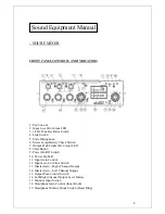
Page 8: ...Limiter Bi Colour LED 8 Slate Button 9 Power On Off Switch 10 Power On LED 11 Input Gain Control 12 Input Low Cut Filter Switch 13 Master Gain Right Channel Output 14 Master Gain Left Channel Output...

Page 9: ...Channel Inputs 2 Mic Line Level Input Switch OUTPUT PANEL CONNECTORS AND CONTROLS 1 Mix Bus Jack 2 Main Output 3 Headphones Outputs 4 Monitor In Jack 5 Tape Output Jack 6 Mic Line Level Output Switch...

Page 10: ...ape that is separate from the video information Sound waves are vibrations in the air There are 2 basic properties frequency and amplitude Frequency from low to high Amplitude from soft to loud Togeth...

Page 11: ...on the back of the camcorder Audio 2 terminals are on the right side of the handle Stereo 1 and Stereo 2 refer to the stereo tracks available on the tape Audio Monitor only use when using 12 bit Stere...

Page 12: ...ugged into the mini jacks 3 5mm mini plug type 1 Open the Camera Menu Select AUDIO MODE Choose one of the following modes a 16 bit 48kHz 2 channel for the highest sound quality Note the 16 bit mode co...

Page 13: ...t AUDIO MODE and choose one of the following modes a 16 bit 48KHz 2 channel for the highest sound quality Note the 16 bit mode contains only Stereo 1 sound There is no Stereo 2 in this mode b 12 bit S...

Page 14: ...the highest sound quality Note the 16 bit mode contains only Stereo 1 sound There is no Stereo 2 in this mode b 12 bit Stereo 1 32kHz 2 out of 4 total channels for recording on 2 channels Stereo 1 lea...

Page 15: ...2 is displayed in the viewfinder and main LCD panel Selecting Audio Mode 12 bit ST 1 2 32kHz 4 channels is for simultaneous recording on four channels referred to as Stereo 1 and Stereo 2 2 To set th...

Page 16: ...MIC controls to M Turn the LEVEL dial to adjust the recording level and BALANCE dial to adjust the balance between the two inputs Check the levels in the audio LCD panel b Set the recording level for...

Page 17: ...ricity outside of it professional cable analogue cable carrying an analogue signal 2 Kettle plug carries current electricity controls behaviour of devices carries only electricity not audio or video 3...

Page 18: ...h 1 Spatial compression affects only a single frame at a time This type of compression makes random access to any point in the video and editing easy Spatial compression finds redundancy within a fram...

Page 19: ...mes and B frames The content of a P frame predictive frame is based on the previous frame the content of a B frame bi directional frame is based on the previous and subsequent frames Audio compression...
Page 20: ...lies quite well Tilts and pans are more difficult Depending on the codec rotating the camera a Dutch can be trivial or extremely costly in compression efficiency The most difficult motion for any code...

Page 21: ...ttenuation or the loss of signal power and quality over long cable runs usually 300 meters or more Equipment that supports analogue signals is generally more affordable and analogue video formats are...

Page 22: ...e susceptible to interference so they are not often used in professional applications There are three basic kinds of unbalanced audio connectors The most familiar to consumers is traditional unbalance...

Page 23: ...time Motion JPEG is 4 2 2 and most implementations allow you to specify a data rate or quality level 3 Uncompressed codecs More and more cards support true 4 2 2 uncompressed video The data rates are...

Page 24: ...file formats for rendering The most common formats are QuickTime and AVI both offer good quality intermediate codecs You can also use MPEG 2 at high data rates Modern tools like After Effects and Adob...

Page 25: ...me size for example going from a 720 x 480 source frame to a 320 x 240 output frame for web video Scaling up on either axis forces a video editing application to make up data that s not in the source...

Reviews: