background image

Installation Procedure

1. Open the Front Cover.

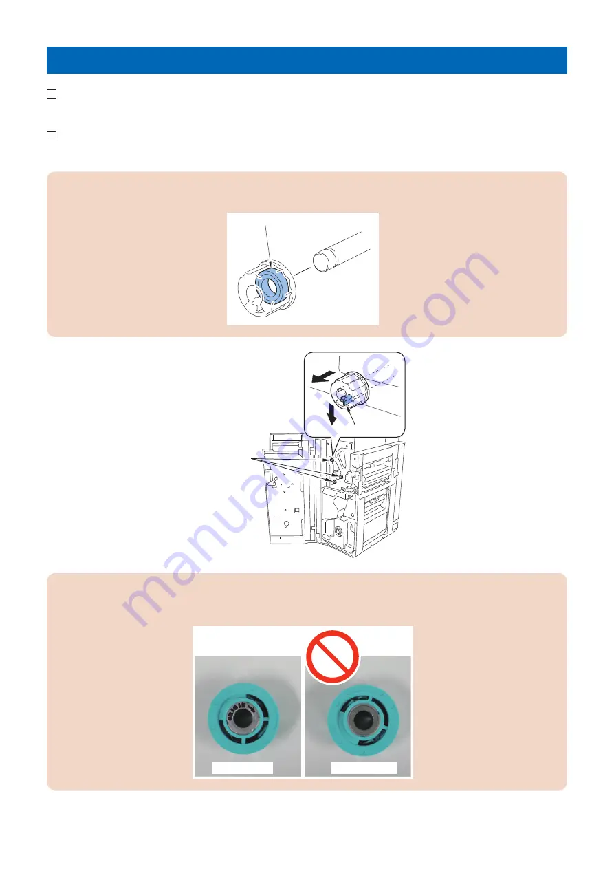
2. Push the claw in the direction of the arrow[A] and remove the 3 knobs in the direction of the arrow[B].

CAUTION:

Be careful not to drop the bearing inside the knob.

Bearing

[A]

[B]

Claw

Knobs

CAUTION:

• If the bearing fell off from the knob, reattach it.
• A bearing has the orientation so make sure to install it in the correct direction.

No inscription

With inscription

4. Installation

19

Summary of Contents for Puncher Unit-BS1

Page 1: ...SERVICE MANUAL Puncher Unit BS1 BT1 BU1 COPYRIGHT 2015 CANON INC CANON Puncher Unit BS1 BT1 BU1 Rev 1 PRINTED IN U S A October 6 2015 Rev 1 ...

Page 2: ...a long or short period Canon will issue a new edition of this manual The following paragraph does not apply to any countries where such provisions are inconsistent with local law Trademarks The product names and company names used in this manual are the registered trademarks of the individual companies Copyright This manual is copyrighted with all rights reserved Under the copyright laws this manu...

Page 3: ... door and closing the delivery unit door which results in supplying the machine with power 2 In the digital circuits 1 is used to indicate that the voltage level of a given signal is High while 0 is used to indicate Low The voltage value however differs from circuit to circuit In addition the asterisk as in DRMD indicates that the DRMD signal goes on when 0 In practically all cases the internal me...

Page 4: ...ystem 14 Remove the punch unit 14 4 Installation 15 Points to Note at Installation 16 How to check this Installation Procedure 16 Symbols in the Illustration 16 Points to Note before Installation 17 Check Items when Turning OFF the Main Power 17 Checking the Contents 18 Installation Procedure 19 Adjustments 27 Punching Operation Settings 27 Punch Blade Home Position Adjustment ForFinisher AM1 AN1 ...

Page 5: ...Safety Precautions Notes Before it Works Serving 2 Points to Note at Cleaning 2 ...

Page 6: ... a sheet of paper under the parts to prevent them from being soiled or foreign matter from entering the parts Before installing the parts to the host machine ensure that they are free of foreign matter Points to Note at Cleaning CAUTION When performing cleaning using organic solvent such as alcohol be sure to check that the component of solvent is vaporized completely before assembling Safety Prec...

Page 7: ...Product Overview 1 Specifications 4 Names of Parts 6 ...

Page 8: ...rm 2 hole 182 to 432 x 182 to 297 3 hole 182 to 432 x 240 to 297 4 hole Puncher Unit BU1 A3 A4 indeterminate form 182 to 432 x 257 to 297 Paper weight 52g m2 to 300g m2 Transparency and tracing paper cannot be used In the case of coated paper 80 to 209 g m2 Punch hole diameter 2hole 6 5 mm 2 3hole 8 mm 4hole 6 5 mm Punch chip case equivalent of 6 000 sheets equivalent of 80 g m2 paper Dimensions 7...

Page 9: ... B5 88 5 1mm A4R 65 1mm B5R 51 1mm 2 Puncher Unit BS1 2 3 KROH 69 85 1mm L1 12 1mm LGL LTRR 73 1mm 108 1mm 108 1mm L1 12 1mm LTR 11 x17 31 5 1mm 1 Puncher Unit BU1 4 KROH 70 1mm 21 1mm 21 1mm L1 12 1mm A4 A3 92 5 1mm 80 1mm 80 1mm 80 1mm L1 12 1mm A4 A3 28 5 1mm 1 Product Overview 5 ...

Page 10: ...Names of Parts Cross Section 1 2 3 4 5 No Name No Name 1 Punch Motor 4 Stopper 2 Punch chip case full sensor 5 Pin 3 Punch chip case 1 Product Overview 6 ...

Page 11: ...Technology 2 Feed Drive System 8 ...

Page 12: ...nch Motor Clock Sensor Punch Chip Case Sensor PS40 PS39 Punch 2 3 hole Sensor PS37 Punch Front Sensor PS36 Punch Motor Home Position Sensor Punch Motor M24 Paper Movement PS46 Punch Chip Case Full Sensor Punch Chip Case Inlet Sensor Prism Motor Description Punch motor M24 Drives the Rack slider Sensor Description Punch 2 3hole sensor PS39 Detects the Rack 2 3hole position of the slider Punch clock...

Page 13: ...s the shift transport motor to drive the shift roller Shift Roller Inlet Sensor Shift Roller Shift Transport Motor Inlet Sensor 3 With paper remaining in contact with the shift roller the horizontal shift motor goes on to move the shift roller unit for correction of displacement in horizontal direction Horizontal Registration Motor ShIft Roller Unit 4 After correcting displacement in horizontal re...

Page 14: ...presence absence of the punch chip case The chips occurring as the result of punching operation are collected in the punch chip case and are monitored by a reflection type sensor punch chip case full sensor When the case becomes full with chips the main controller PCB suspends punching operation between stacks Memo resuming the operation when the case is put back in place Punch Chip Case Sensor PS...

Page 15: ...Disassembly Assembly 3 Removing from the Host Machine 12 Drive System 14 ...

Page 16: ... 1 2 Pull out the punch dust container 1 1 3 Remove the rear cover 1 8 screws 2 2 1 2 2 8x 4 Remove the 2 connectors 2 connected to the finisher controller 1 2 2 1 2x 5 Remove the cable of the punch unit 1 edge saddle 2 1 cable guide 3 1 connector 4 2 1 3 4 1x 2x 3 Disassembly Assembly 12 ...

Page 17: ...6 Remove the punch unit 1 2 screws 2 1 2 2x 3 Disassembly Assembly 13 ...

Page 18: ...eparations 1 Remove the punch unit Procedure 1 Remove the sensor plate 1 1 connector 2 3 screws 3 1 2 3 1x 1x 2 Remove the punch motor 1 2 screws 2 1 2 2x 3 Remove the gear 1 and Punch motor 3 2 screws 2 1 2 3 2x 3 Disassembly Assembly 14 ...

Page 19: ...Installation 4 Points to Note at Installation 16 Checking the Contents 18 Installation Procedure 19 Adjustments 27 Affixing the A1 Labels 40 ...

Page 20: ...this Installation Procedure Symbols in the Illustration The frequently performed operations are described with symbols in this procedure 1x 1x 1x Install Screw Packaged Item Remove Tighten Loosen 1x Connect Connector Disconnect Install Harness Common for Guides and Clamps Remove 1x 1x 1x 1x Connect Power Cord Disconnect Check visually Check the sound Check OFF Cleaning ON Push Power Unused Parts 4...

Page 21: ...ncher unit Check Items when Turning OFF the Main Power Check that the main power is OFF 1 Turn OFF the main power switch of the host machine first and then options 2 Be sure that Control Panel Display and Main Power Lamp are both turned OFF and then disconnect the power plug 4 Installation 17 ...

Page 22: ...1 Punch Unit X 1 2 Punch Dust Box Unit X 1 3 Punch Dust Box Frame Unit X 1 4 A1 Label X 1 5 Screw RS tightening M4x8 X 1 Since 2 and 3 are integrated at the shipment separate them to install when unpacking 4 Installation 18 ...

Page 23: ...3 knobs in the direction of the arrow B CAUTION Be careful not to drop the bearing inside the knob Bearing A B Claw Knobs CAUTION If the bearing fell off from the knob reattach it A bearing has the orientation so make sure to install it in the correct direction No inscription With inscription 4 Installation 19 ...

Page 24: ...move the Inner Cover upper 4 Screws 4x Inner Cover Upper Upper Cover 4 Remove tapes from Punch dust box unit 5 Separate the Puncher Dust Box Frame Unit and Puncher Dust Box Unit and remove the tape Punch Dust Box Unit Punch Dust Box Frame Unit 4 Installation 20 ...

Page 25: ... CAUTION When tightening screws press down with the finger to prevent the Puncher Dust Box Frame Unit from moving If the Puncher Dust Box Frame Unit is installed at an angle it will be difficult to install the Puncher Dust Box Unit due to the interference M4x8 1x Hole Punch Box Frame Unit Punch Box Frame Unit Punch Box Frame Unit Positioning Pin 4 Installation 21 ...

Page 26: ...7 Remove the Rear Cover 2 Screws Loosen 6 Screws 6x 2x 4 Installation 22 ...

Page 27: ...tion of the arrow removed guide will not be used 2 Screws removed screws are used in step 10 Guide Screw Screw 2x CAUTION Do not touch the sensor area when holding the puncher unit 9 Removed the tape of the punch unit 4 Installation 23 ...

Page 28: ...d in step 8 CAUTION When inserting the Punch Unit avoid catching the belt with the Guide Plate NOTE Align the Guide Plate of the Finisher with the groove of the Punch Unit 2x Punch Unit Guide Plate Groove Belt 11 Connect the cable Short for the Punch Unit 1 Connector 4 Installation 24 ...

Page 29: ...The remaining length of the cable Long should be left to slack at the Controller PCB B side A B 3x 2x Connector Edge Saddle Cable Long Cable Short Cable Guide 13 Cut the 2 Face Covers of the Inner Cover upper with nippers CAUTION Be sure to remove the Face Covers thoroughly so that no bur is remained Face Covers Nipper 14 Install the Inner Cover upper and the 3 knobs 4 Screws 4 Installation 25 ...

Page 30: ...rrow from the front Punch Dust Box Unit 16 Close the Upper Cover 17 Close the Front Cover 18 Install the Rear Cover 6 Screws 2 Screws Tighten 8x 19 Connect the host Machine with the Finisher referring to Installation Procedure of the Finisher 4 Installation 26 ...

Page 31: ...nstall you may need to make settings of the DIP Switch on the switch PCB found in the Finisher Preparations 1 Open the Front Cover to remove the Switch Cover 1 Screw 1x Screw Switch Cover 2 Open the Front Cover and put the Door Switch Tool into the door switch 4 Installation 27 ...

Page 32: ...S1 2 3 hole punch unit for Puncher Unit BU1 4 hole punch unit for Puncher Unit BT1 2 4 hole punch unit 2 Install the Switch Cover 1 Screw and close the Front Cover 3 Connect the power plugs of the host machine and options to the outlet 4 Turn ON the main power switch of the host machine first and then options 5 Specify the punching operation on the control panel of the Host machine to confirm whet...

Page 33: ...her W1 PRO Booklet Finisher W1 PRO perform this adjustment by all means Because a Punch Blade Home Position Adjustment is not controlled normally unless adjust it be careful 1 Open the Front Cover to remove the Switch Cover 1 Screw 1x Screw Switch Cover 2 Open the Front Cover and put the Door Switch Tool into the door switch 3 Write down the setting of DIP SW while the Switch Cover is removed 4 In...

Page 34: ...o the Finisher AK1 AM1 AN1 Saddle Finisher AK2 AM2 AN2 Staple Finisher W1 PRO Booklet Finisher W1 PRO Checking Adjustment Value 1 Write down the setting of DIP Switch SW382 whose state is before being adjusted 2 Set DIP switch SW 382 on the Switch PCB as shown in the figure 1 4 6 8 ON and press ENTER button SW 385 resulting in 0 blinks on the LED SW382 SW381 SW383 ENTER SW384 SW385 DSP381 3 Place ...

Page 35: ...estore the DIP Switch setting to the state of Step 1 and install the Switch Cover with a screw removed in the previous step 7 Remove the door switch tool 8 Close the Front Cover 9 If the adjustment value estimated value is out of the range execute Side registration adjustment or Skew adjustment Side Registration Adjustment 1 Execute shutdown sequence and then turn OFF the power of the host machine...

Page 36: ...in A direction and tighten the 2 screws If the value obtained at Checking Adjustment Value is negative move it in B direction and tighten the 2 screws B A 2x 2x Screw Skew Adjustment CAUTION If the skew adjustment value is within the range start from step 8 4 Installation 32 ...

Page 37: ...n of the arrow B CAUTION Be careful not to drop the bearing inside the knob Bearing A B Claw Knobs CAUTION If the bearing fell off from the knob reattach it A bearing has the orientation so make sure to install it in the correct direction No inscription With inscription 4 Installation 33 ...

Page 38: ... Cover in the direction of the arrow and remove the Inner Cover upper 4 Screws 4x Inner Cover Upper Upper Cover 3 Remove the Latch Base Cover 3 Screws 3x 4 Loosen the 2 screws on the Latch Plate Front 4 Installation 34 ...

Page 39: ...d at Checking Adjustment Value is negative move it in B direction and tighten the 2 screws CAUTION Perform adjustment so that the total of the shifting amount scale of the Latch Plate Front Rear is within 2 to 2 mm 2x 2x A B Screw 6 Remove the Rear Small Cover 1 Screw 1x 7 Loosen the 2 screws on the Latch Plate Rear 4 Installation 35 ...

Page 40: ... host machine 11 Check the adjustment value again If the adjustment value indicated on the LED is within the range press ENTER button SW385 to complete the adjustment mode If the adjustment value indicated on the LED is out of the range execute adjustment for the second time Adjustment can be considered OK to complete if the value gets closer to the adjustment range estimated value 12 Put the DIP ...

Page 41: ...Stop position of paper Stopper 1 Open the Front Cover and insert the door switch tool into the door switch 4 Installation 37 ...

Page 42: ...s shown in the figure below 1 5 6 8 ON Once pressing the ENTER SW 385 button the LED shows 0 SW382 SW381 SW383 ENTER SW384 SW385 DSP381 LED DIP Switch SW382 ENTER SW385 Button 4 When executing punching operation in this condition the paper stops without switchback and holes are punched 4 Installation 38 ...

Page 43: ... 2 0 mm or less A A Paper Stop Position Adjustment value SW 384 Increase One press 0 4 mm SW 383 Decrease 6 Perform punching operation again to verify the paper stop position If the measured value is beyond the adjustment value rnge Repeat adjustment until the measured value is within the adjustment value range If the measured value is within the adjustment value rnge Press the ENTER button to ter...

Page 44: ...Affixing the A1 Labels 1 Open the Front Cover 2 Affix the Operation Label and Jam Recovery Label to the Inner Cover Upper Operation Label Jam Recovery Label 3 Close the Front Cover 4 Installation 40 ...

Reviews: