
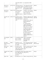


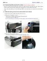
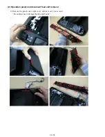


- Keep the timing slit strip film (carriage
encoder film) free from stain or damage.
When returning the film, make sure of its
orientation (left and right, front and back).
- See
2-2. Disassembly & Reassembly
Procedures, (7) Carriage unit removal
, for
details.
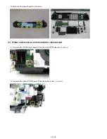
Switch
system
unit
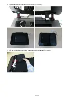
(1) Cassette unit
(2) Left and right side covers
(3) Document pressure plate unit
(4) Scanner unit
(5) Main case
(6) Rear cover
(7) Print unit
(8) See
2-2. Disassembly & Reassembly
Procedures
.
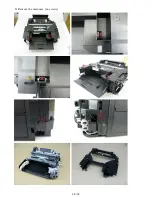
- See
2-2. Disassembly & Reassembly
Procedures, (9) Purge drive system unit
(right plate) and switch system unit (left
plate) removal
, for details.
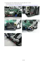
- See
2-2. Disassembly & Reassembly
Procedures, (10) Engine unit reassembly
,
for details.
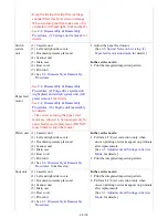
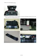
- The screws securing the paper feed
motor are allowed to be loosened only for
paper feed motor replacement. (DO NOT
loosen them in any other cases.)
1. Adjust the paper feed motor.
[See
3-6. Special Notes on Servicing, (2)
Paper feed motor adjustment
, for details.]
In the service mode:
2. Print the integrated inspection pattern.
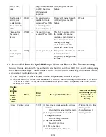
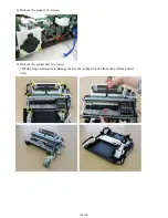
Paper feed
motor
Platen unit (1) Cassette unit
(2) Left and right side covers
(3) Document pressure plate unit
(4) Scanner unit
(5) Main case
(6) Rear cover
(7) Print unit
(8) See
2-2. Disassembly & Reassembly
Procedures
, from this step.
In the service mode:
1. Perform LF / Eject correction (only when
uneven printing or streaks appear on printouts
after replacement).
[See
3-3. Adjustment and Settings in Service
Mode
, for details.]
2. Print the integrated inspection pattern.
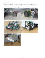
Spur unit
(1) Cassette unit
(2) Left and right side covers
(3) Document pressure plate unit
(4) Scanner unit
(5) Main case
(6) Rear cover
(7) Print unit
(8) See
2-2. Disassembly & Reassembly
Procedures
.
In the service mode:
1. Print the integrated inspection pattern.
2. Perform LF / Eject correction (only when
uneven printing or streaks appear on printouts
after replacement).
[See
3-3. Adjustment and Settings in Service
Mode
, for details.]
20 / 76
Summary of Contents for PIXMA MX882 Series
Page 32: ...8 Remove the main case no screws 28 76...
Page 35: ...4 Remove the LCD ass y no screws 31 76...
Page 55: ...2 Service Tool functions Service Tool screen Version 2 000 51 76...
Page 56: ...52 76...
Page 67: ...63 76...
Page 74: ...4 2 Integrated Inspection Pattern Print Print sample...
Page 75: ...4 3 Ink Absorber Counter Value Print Print sample 4 VERIFICATION AFTER REPAIR...
Page 78: ......


