Canon PIXMA MP610 Series Service Manual Download Page 11

2-4.  Warnings 


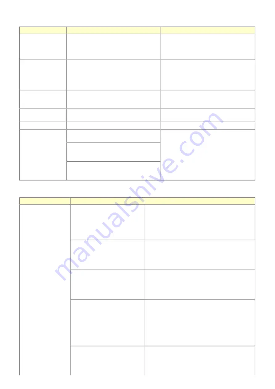
2-5.  Troubleshooting by Symptom 

Warning

Message on the LCD

Solution

Low ink

"!" is indicated for an applicable ink tank icon in 
the Status Monitor.

No special solution. 

Since the ink will be used up soon, prepare for a 
new ink tank. 

Print head temperature 
rise

If the print head temperature does not fall, the print 
head error will occur.

When the print head temperature falls, the error is 
automatically cleared. 

If the print head error is indicated, repair servicing 
is required. 

Protection of excess rise 
of the print head 
temperature

If the print head temperature does not fall, the print 
head error will occur.

If the print head temperature exceeds the specified 
limit, an intermission is inserted during printing.

Restrictions on paper

The current paper cannot be set. Change the size 
and type.

Re-select the supported paper type and size.

USB cable not connected Set the PC to start scan.

Connect the USB cable, then turn on the computer.

Cancellation of image 
select information

Reset the selected photo information?  
Yes     No

- Select 

Yes

, and press the OK button. 

=> The image selection is cancelled, and the 

menu or sub-menu is displayed. 

- Select 

No

, and press the OK button. 

=> The LCD returns to the display immediately 

before the message was displayed. 

Do you want to clear the image scanned from the 
photo?  
Yes     No

Do you want to clear the scanned image and 
rescan?  
Yes     No


Symptom

Solution

Faulty operation

The power does not turn on. 
The power turns off immediately after 
power-on.

- Confirm the connection of 

- the power cord, and  
- between the logic board and the power supply unit.  

- Replace the 

- power supply unit, or 
- logic board. 

A strange noise occurs.

- Remove foreign material. 
- Attach a removed part if any. 
- Check the operation of the moving parts (such as purge 

unit, carriage unit, and paper feeding mechanism) 

- Replace a faulty part, if any. 

Nothing is displayed on the LCD.

- Confirm the connection between the operation panel, the 

LCD unit, and the logic board. 

- Replace the 

- operation panel unit, or 
- logic board. 

A portion of the LCD is not displayed. 
The display flickers. 

- Perform the button and LCD test in the service mode, and 

confirm that the LCD is displayed without any segments 
missing or flickering. 

- Confirm the connection between the operation panel, the 

scanning unit, and the logic board. 

- Replace the 

- operation panel unit, or 
- logic board. 

Paper feed problems (multi-feeding, 
skewed feeding, no feeding).

- Examine the inside to confirm that no parts are damaged, 

and the rollers are clean. 

- Remove foreign material. 
- Adjust the paper guide properly. 

9 / 43

Summary of Contents for PIXMA MP610 Series

Page 1: ...ographical errors due to improvements or changes made to the product When changes are made to the contents of the manual Canon will release technical information when necessary When substantial changes are made to the contents of the manual Canon will issue a revised edition The following do not apply if they do not conform to the laws and regulations of the region where the manual or product is u...

Page 2: ... scanner unit and document cover removal 2 Operation panel removal 3 Cable wiring and connection 4 Emblem removal 5 Printer unit separation from the bottom case how to remove the screw under the purge unit 3 3 Adjustment Settings 1 Paper feed motor adjustment 2 Document pressure plate sheet sponge sheet replacement 3 Grease application 4 Ink absorber counter setting 5 User mode 6 Service mode A Se...

Page 3: ... that the belt is stretched tight None 5 min CD DVD detection sensor light volume correction 1 At carriage unit replacement At logic board replacement To correct the light volume for the CD DVD detection sensor None Perform in the service mode 5 min Automatic print head alignment At print head replacement At logic board replacement When print quality is not satisfying To secure the dot placement a...

Page 4: ...eding eject roller diameter None Perform in the service mode DO NOT loosen the red screws at both ends of the carriage shaft securing the print head position as they are not re adjustable The red screws securing the paper feed motor may be loosened only at replacement of the paper feed motor unit For the automatic print head alignment use Matte Photo Paper MP 101 which is packed with the machine b...

Page 5: ...f the rear tray Machine buttons Computer MP driver 2 min Rear tray sub roller cleaning When the paper fed from the rear tray is smeared due to ink mist attached to the rear tray sub rollers To clean the rear tray sub rollers Machine buttons 1 min Bottom plate cleaning When the back side of the paper is smeared To clean the platen ribs Machine buttons Computer MP driver 1 min Scanning area cleaning...

Page 6: ...the proper position Then press the OK button No paper in the cassette 1003 Cassette There is no paper Load paper and press OK Confirm that the cassette is selected as the paper source Set the paper in the cassette and press the OK button Paper jam 1300 The paper is jammed Clear the paper and press OK Remove the jammed paper and press the OK button Paper jam in the rear guide 1303 Paper jam in the ...

Page 7: ...ration See manual Press the OK button to clear the error then perform the automatic print head again In the MP610 use Matte Photo Paper MP 101 The remaining ink amount unknown 1683 U130 Applicable ink tank icon The remaining level of the following ink cannot be correctly detected Replace the ink tank An ink tank which has once been empty is installed Replace the applicable ink tank with a new one ...

Page 8: ... be full Message on the LCD Ink absorber full Service required Error codes 5B00 Main ink absorber is full overseas 5B01 Main ink absorber is full Japan Ink absorber kit 8 times Print head temperature rise error 5200 The print head temperature exceeded the specified value Print head Logic board 9 times EEPROM error 6800 A problem occurred in writing to the EEPROM Logic board 10 times VH monitor err...

Page 9: ...Reduce the amount of photos films copies to scan The memory is not sufficient to do the print job in copying Reduce the amount of data to be printed or print from a computer Press Color button icon The Black button was pressed but it is invalid A temporary error Press the Color button to continue the operation Press Black button icon The Color button was pressed but it is invalid A temporary error...

Page 10: ...the circles on the Photo Index Sheet Place the sheet in the correct orientation and position Failed to scan handwriting sheet Check orientation and position and make sure platen and sheet are clean See manual The machine failed in scanning the handwritten Photo Index Sheet Failed to scan DVD CD handwriting sheet Check orientation and position and make sure platen and sheet are clean The machine fa...

Page 11: ...K button The LCD returns to the display immediately before the message was displayed Do you want to clear the image scanned from the photo Yes No Do you want to clear the scanned image and rescan Yes No Symptom Solution Faulty operation The power does not turn on The power turns off immediately after power on Confirm the connection of the power cord and between the logic board and the power supply...

Page 12: ... the orange tape is properly removed from an ink tank and the ink tanks are installed properly Perform print head maintenance Replace the ink tank print head 1 Remove foreign material from the purge unit caps if any Replace the purge unit or logic board Printing is faint or white lines appear on printouts even after print head cleaning Line s not included in the print data appears on printouts Rem...

Page 13: ...ed on printouts When enlarged in the carriage movement direction Clean grease or oil off the timing slit strip film Replace the timing slit strip film carriage unit logic board or scanning unit when copying When enlarged in the paper feed direction Clean grease or oil off the timing slit disk film or the timing slit disk eject film Replace the timing slit disk film timing slit disk eject film timi...

Page 14: ...Copying Direct printing from a digital camera PictBridge Absorber kit After replacement 1 Reset the ink absorber counter See 3 3 Adjustment Settings 6 Service mode for details Ink absorber counter volume print After the ink absorber counter is reset the counter value is printed automatically Carriage unit At replacement 1 Apply grease to the sliding portions See 3 3 Adjustment Settings 3 Grease ap...

Page 15: ...iage shaft positioning they are not adjustable in servicing Easy Scroll Wheel base See 3 3 Adjustment Settings 3 Grease application for details Document pressure plate unit After replacement 1 Confirm the document pressure plate sheet position See 3 3 Adjustment Settings 2 Document pressure plate sheet replacement for details 2 Check the LCD and operation panel See 3 3 Adjustment Settings 6 Servic...

Page 16: ...ove the cassette 2 Open the front door and scanner unit then remove the side cover R 3 screws While slightly pulling up the back of the scanner unit remove the side cover R The side cover R holds the scanner unit hinge 3 Remove the document cover document pressure plate unit While slightly pushing the left and right hinges toward the center pull the cover upward to remove it The cover will not be ...

Page 17: ...s the scanner unit hinge Since the pressure of the scanner lock arm spring is in the upward direction hold the scanner unit while removing the side cover In the left back of the scanner unit the ground wire is fastened to the chassis Be cautious of it 15 43 ...

Page 18: ...gage the scanner lock arm from the scanner unit While rotating the scanner unit slightly toward the outside release the scanner lock arm from the scanner unit Photo up Scanner unit Photo on the left Machine after the scanner unit is removed Remove the scanner lock arm or paper support when necessary 16 43 ...

Page 19: ...6 Remove the main case Release the 4 claws and pull up the main case no screws 17 43 ...

Page 20: ...op cover from the base while exercising caution not to break the claws 2 Remove the panel frame from the top cover 6 screws The FFC core is fixed to the unit with filament tape as shown in the photo Pull the operation panel cover upward to remove it There are 4 claws each in the front and in the back 18 43 ...

Page 21: ...les While moving the hinge to compress the spring remove the LCD from the panel frame Remove the panel chassis and panel board 6 screws 4 Remove the Easy Scroll Wheel from the panel board Be cautious not to touch the grease between the wheel and the wheel base See 3 3 Adjustment Settings 3 Grease application 19 43 ...

Page 22: ... bottom case Be cautious of the position of the screw that fixes the ground wire The ground wire passes through the same cores as the card harness 2 Seen from the back side of the machine Note the DC harness position 3 Right side of the machine AC adapter and bottom case removed 20 43 ...

Page 23: ...urge unit Push the emblem bottom to remove from the double sided adhesive tape 1 Rotate the purge unit gear toward the rear side of the machine to unlock the carriage 2 Slide the carriage to the opposite of the home position to the left and remove the screw 3 2 Special Notes on Repair Servicing 21 43 ...

Page 24: ... pressure plate sheet With the long side down position the lower right corner of the document pressure plate sheet at the scanning reference point on the platen glass front right where the red lines cross in the photo above 2 Slowly close the document pressure plate while maintaining the hinge position The document pressure plate sheet will attach to the plate 3 Open the plate to confirm the follo...

Page 25: ...t shaft cam contact portion 3 locations 6 Floil KG107A 18 to 27 1 5 x 3 7 Idler pulley The shaft surface which contacts the idler pulley hole 7 Floil KG107A 9 to 18 1 x 1 8 Carriage shaft Entire surface of the carriage shaft where the carriage unit slides 8 Floil KG107A 200 to 400 9 Carriage shaft spring L Carriage shaft sliding portion to the end of the spring 9 Floil KG107A 9 to 18 1 x 1 10 Carr...

Page 26: ...24 43 ...

Page 27: ...he applicable ink absorber counter to 0 How to check the ink absorber counter value See 3 4 Verification Items 1 Service test print How to set the ink absorber counter See 3 3 Adjustment Settings 6 Service mode Ink absorber counter setting No Part name Where to apply grease oil Drawing No Grease oil Grease oil amount mg Number of drops x locations 15 Easy Scroll Wheel base Easy Scroll Wheel slidin...

Page 28: ... head alignment Perform via the machine operation panel or from the MP driver Maintenance tab If automatic alignment is not effective perform manual print head alignment 2 sheets of A4 Matte Photo Paper Manual print head alignment Perform via the machine operation panel or from the MP driver Maintenance tab Set 4 sheets of plain paper A4 or Letter in the rear tray or the cassette which is selected...

Page 29: ...ed 1 time Orange Alarm Service test print Service test print Model name ROM version Ink absorber counter value ink amount in the ink absorber USB serial number Destination EEPROM information Ink system function check result Barcode model name destination See 3 4 Verification Items 1 Service test print Service test print sample 2 times Green Power EEPROM information print EEPROM information print M...

Page 30: ...ot used in servicing 9 times Orange Alarm CD DVD print position correction vertical Y direction Not used in servicing 10 times Green Power LF Eject correction See LF Eject correction below 11 times Orange Alarm Left margin correction Not used in servicing 12 times Green Power Button and LCD test See Button and LCD test below 13 times Orange Alarm Ink absorber counter setting See Ink absorber count...

Page 31: ...enter the ink absorber counter setting mode 3 In the ink absorber counter setting mode press the ON OFF button again to enter the main ink absorber counter setting mode Since the procedure for setting the ink absorber counter is common among all the models this step is necessary to set the counter value for the main ink absorber 4 The ink absorber counter value can be set in 10 increments by press...

Page 32: ...nstead of the E MIP correction value thus in the initial EEPROM information print LF and EJ are printed 1 In the LF Eject correction mode press the Stop Reset button the specified number of time s according to the paper to be used in LF Eject correction listed in the table below then press the ON OFF button Set a sheet of selected paper in the rear tray Time s Ink absorber counter value to be set ...

Page 33: ...2 The LF Eject correction pattern for the selected paper is printed LF correction values from 0 to 2 on the left Eject correction values from 0 to 2 on the right 31 43 ...

Page 34: ...correction becomes ON and the machine returns to the service mode menu selection Selected pattern number Number of times the Stop Reset button is pressed M 1 1 time 0 0 times 2 2 times Each time the Stop Reset button is pressed the Alarm and Power LEDs light alternately Alarm in orange and Power in green If the Stop Reset button is pressed 3 times or more then the ON OFF button is pressed the mach...

Page 35: ...LF Eject correction flowchart 33 43 ...

Page 36: ...om the cassette The pattern is printed on both sides of paper duplex printing A total of 4 sheets are ejected After this set the correction value to the EEPROM in the steps below 2 Selection of the parameter mode for left margin correction Press the Stop Reset button the specified number of time s according to the parameter mode listed in the table below then press the ON OFF button Each time the ...

Page 37: ...fed from the cassette and back side of paper fed from the cassette 4 After the left margin correction in all the parameter modes is completed press the Stop Reset button 4 times or more in the parameter mode selection then press the ON OFF button to return to the service mode menu selection Number of times the Stop Reset button is pressed N Left margin correction value 0 times Return to the parame...

Page 38: ...Left margin correction flowchart 36 43 ...

Page 39: ...37 43 ...

Page 40: ... corresponding to the number of steps the wheel is rotated counterclockwise returns to red If the wheel keeps rotated clockwise over 1 round 24 steps the color of segment s corresponding to the extra number of steps returns to red starting with the Start segment in the figure below 4 2 When the Easy Scroll Wheel is rotated clockwise 1 round 24 steps press the OK button 4 3 Rotate the Easy Scroll W...

Page 41: ...he OK button OK1 in white is displayed on the black background If the result is not good NG1 in black is displayed on the white background transparent color immediately after OK1 5 2 Press the OK button OK2 in black is displayed on the white background If the result is not good NG2 in white is displayed on the black background transparent color immediately after OK2 5 3 Press the OK button The mac...

Page 42: ... bottom of the Y N VrefPWM MIN 32h VrefPWM 2 Current VrefPWM value hexadecimal at the bottom of the LCD Writing of the VrefPWM value to the EEPROM Reading of the VrefPWM value from the EEPROM N Y Initial VrefPWM value 50h 2 5 inch model VrefPWM register setting Press OK Press Press VrefPWM 16 START From 01h to 1Fh hexadecimal Adjustment end Decrease VrefPWM key END 3 3 Adjustment Settings 5 and 6 ...

Page 43: ...3 4 Verification Items 1 Service test print Service test print sample MP610 3 REPAIR TABLE OF CONTENTS 41 43 ...

Page 44: ... 2 Ink absorber counter value print Print sample 3 4 Verification Items 42 43 ...

Page 45: ...e See Caution 2 below If the print head must be removed from the machine and transported alone attach the protective cap used when the packing was opened to the print head to protect the print head face from damage due to shocks MP610 TABLE OF CONTENTS 1 If the print head is removed from the machine and left alone by itself ink the pigment based black ink in particular is likely to dry For this re...

Reviews: