background image

Copier B/W | imagePRESS 1135/1125/1110 Series |

E5B5-xx16 due to sliding failure of the waste stopper in the waste
paper case assembly(Perfect Binder-A1,Perfect Binder-C1 )

[Symptom]

E5B5-xx16 error may occur during bookbinding operation.
- E5B5-xx16 error: Waste detection error of Perfect binder

[Cause]

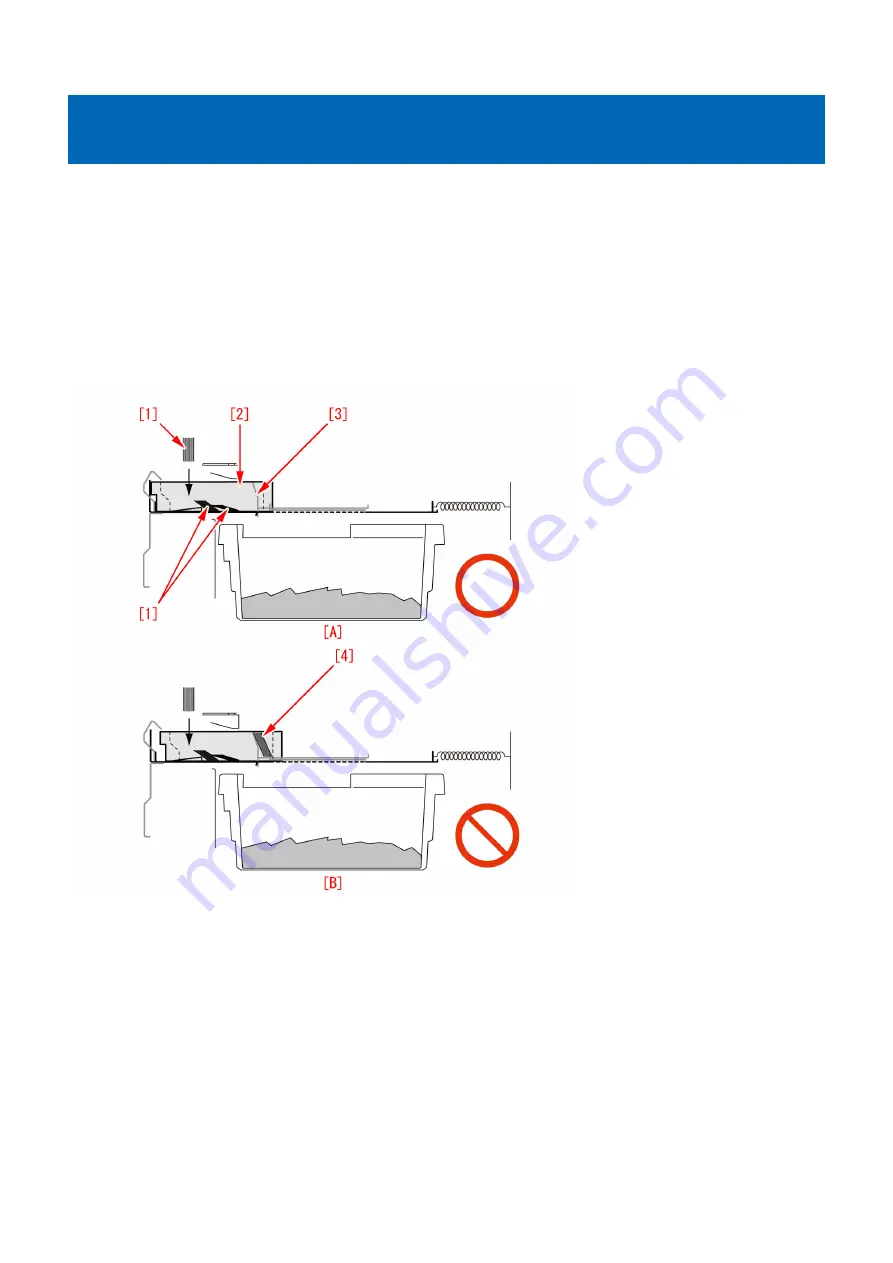
Waste paper [1], generated upon trimming, normally falls into the waste paper buffer [2]. In some cases, the waste paper [1] may
go into the space [4] between the waste paper buffer and the waste stopper [3]. If the waste paper goes in the space, the frictional
resistance increases at the front of the waste stopper. This prevents proper operation, resulting in the symptom.
Figure [A] below shows paper waste that has properly fallen. Figure [B] shows the state in which waste paper has gone into the
space between the waste paper buffer and the waste stopper.

[Service work]

When the above mentioned symptom has occurred, prepare and replace with the Dust Stopper Unit (FM1-D248-000) following
the procedure below. The procedure below starts from the step after disconnected Perfect binder from the copier main body.

1) Checking sliding failure of the Waste stopper
1-1) Open the front cover (Right/Left).
1-2) While holding the front cover (Left), remove the upper/lower hinges to remove the front cover (Left). Pull the hinge in the
direction of arrow while pushing the black lever to remove the hinge.

134

Summary of Contents for Perfect Binder A1

Page 1: ...Troubleshooting Guide Perfect Binder A1 B1 C1 D1 E1 July 16 2019 Canon U S A Inc ...

Page 2: ...eshooting Guide for Perfect Binder Troubleshooting Guide is a booklet compiled from FAQs issued by Canon Inc Additional case s 1FA5 Jam code due to wear of the roller in the signature delivery assembly Perfect Binder C1 Trouble Shooting Guide will be issued in the future when we have a new issue FAQ ...

Page 3: ...inder D1 74 E5B5 xx16 due to fractured hook arm in the waste paper case assembly Perfect Binder A1 Perfect Binder C1 82 E5B5 xx16 due to fractured hook arm in the waste paper case assembly Perfect Binder B1 Perfect Binder D1 108 E5B5 xx16 due to sliding failure of the waste stopper in the waste paper case assembly Perfect Binder A1 Perfect Binder C1 134 E5B5 xx16 due to sliding failure of the wast...

Page 4: ...ox is housed Caused by the detection sensor bracket deformed PerfectBinder A1 PerfectBinder C1 251 A warning message may be displayed and stay on even if the waste paper box is housed Caused by the detection sensor bracket deformed PerfectBinder B1 PerfectBinder D1 PerfectBinder E1 262 ii ...

Page 5: ...t and last pages of glued stacked of sheets due to the edges of round holes a of mini gripper 1 being located at the upper and lower sides of main gripper assembly when transferring Service work If the above mentioned symptom occurs prepare the sheet kit 4Y8 3138 000 to affix the sheet on the mini gripper being located on the upper and lower sides of main gripper assembly 1 Turn off the main power...

Page 6: ...TION To keep the machine running in service mode be sure to do so with the trimming assembly stowed inside 6 Plug the power cord in the wall outlet 7 Turn on the power switch and then perform machine initialization operation 8 Turn off the power switch 9 Turn on SW1 1 on the service PCB and set the machine in service mode 4 ...

Page 7: ...ce PCB and then press the push switch PSW1 3 three times to stop the mini gripper at the vertical position 12 Turn off the main switch and unplug the power cord from the wall outlet 13 Remove the filter case unit 3 screws 14 Remove the glue transport stay 1 screw 5 ...

Page 8: ...pers 1 2 screw Attention Be careful not to drop the screws into the machine during the operation 16 Stand in front of the machine to face the front side and then remove screws 2 fixing the mini gripper 1 2 screw Attention Be careful not to drop the screws into the machine during the operation 17 Remove the screw 2 being the left side of mini gripper 1 on your left and then disconnect the fixed gro...

Page 9: ...hat 1 one mini gripper 2 has been taken from the back side of machine 20 Prepare the sheet kit 4Y8 3138 000 to affix the sheet on the mini gripper removed from the main gripper along the following reference lines Affixing reference line a Affix the left edge of sheet 1 at where it is within 1mm from the edge of mini gripper Affixing reference line b Affix the upper edge of sheet 1 at where it is w...

Page 10: ...tion of unit 1 being the side of mini gripper is correct and then put the mini gripper Photo A shows upside down position of the unit on the side of mini gripper Photo B shows the correct position Service parts No Part Number Description Q ty Fig No 1 Old P51 New 4Y8 3138 000 SHEET KIT 0 1 8 ...

Page 11: ...t on the first and last pages of glued stacked of sheets due to the edges of round holes a of mini gripper 1 being located at the upper and lower sides of main gripper assembly when transferring Service work If the above mentioned symptom occurs prepare the sheet kit 4Y8 3138 000 to affix the sheet on the mini gripper being located on the upper and lower sides of main gripper assembly 1 Turn off t...

Page 12: ...ION To keep the machine running in service mode be sure to do so with the trimming assembly stowed inside 6 Plug the power cord in the wall outlet 7 Turn on the power switch and then perform machine initialization operation 8 Turn off the power switch 9 Turn on SW1 1 on the service PCB and set the machine in service mode 10 ...

Page 13: ...e PCB and then press the push switch PSW1 3 three times to stop the mini gripper at the vertical position 12 Turn off the main switch and unplug the power cord from the wall outlet 13 Remove the filter case unit 3 screws 14 Remove the glue transport stay 1 screw 11 ...

Page 14: ...pers 1 2 screw Attention Be careful not to drop the screws into the machine during the operation 16 Stand in front of the machine to face the front side and then remove screws 2 fixing the mini gripper 1 2 screw Attention Be careful not to drop the screws into the machine during the operation 17 Remove the screw 2 being the left side of mini gripper 1 on your left and then disconnect the fixed gro...

Page 15: ...at 1 one mini gripper 2 has been taken from the back side of machine 20 Prepare the sheet kit 4Y8 3138 000 to affix the sheet on the mini gripper removed from the main gripper along the following reference lines Affixing reference line a Affix the left edge of sheet 1 at where it is within 1mm from the edge of mini gripper Affixing reference line b Affix the upper edge of sheet 1 at where it is wi...

Page 16: ...tion of unit 1 being the side of mini gripper is correct and then put the mini gripper Photo A shows upside down position of the unit on the side of mini gripper Photo B shows the correct position Service parts No Part Number Description Q ty Fig No 1 Old P51 New 4Y8 3138 000 SHEET KIT 0 1 14 ...

Page 17: ...nation to the above Adjusting work is performed wrongly A Service Mode SORTER Adjust GLUING is adjusted This service mode is specified as unused in imagePRESS 1135 service manual However this service mode might be adjusted in field The parameter of this service mode is adjusted as a reference position of the gap between stack of sheets Signature and the glue spreading roller at the time of being s...

Page 18: ...service mode and Fine adjustment of spread amount of glue in perfect binding in user mode Fine adjustment of spread amount of glue in perfect binding in User Mode Additional Functions System Settings Device Settings is to execute fine adjustment of spread amount of glue that is indicated in the service mode GLU AMT1 to 6 The table below shows the relationship between 6 levels of service mode and 4...

Page 19: ... the sample of main parameters adjustable range 20 to 20 Service work Perform the work of adjusting the glue amount in the order below Adjusting the glue amount for plain paper 1 Check the condition of paper 2 Check the GLUING parameter on the service label affixed inside the front right door of Perfect Binder 3 Check the GLUING parameter of service mode of the device and enter an adjustment value...

Page 20: ... 1 1 Select Additional Functions System Settings Paper Type Management Settings 1 2 Select the paper type to edit from the list and Details Edit 1 3 Press Change in Curl Correction Level 1 4 Press and to adjust the correction level for printing in face up down modes respectively Adjusting in opposite direction of warpage cancels curl out Perform test copy or print with the paper after adjusting an...

Page 21: ...condition of the stack registration guide before adjusting the glue amount and perform cleaning as needed 5 Print out a sample booklet of stack thickness 0 to 1 4mm Print out a booklet of stack thickness 0 to 1 4mm using the stack of sheets Signature checked in the step 1 6 Check the condition of glue applied to the booklet and adjust the glue amount Check the condition of glue applied to the book...

Page 22: ...b Spine glue is pushed and spread over in a T L letter shape or an excessive amount of glue If an excessive amount of glue is applied it generates Spine glue spread over in a T L letter shape C or An excessive amount of glue D In such a case go to Service mode SORTER Adjust GLU AMT1 and adjust by one toward minus direction However as to the spine glue spread over in a T L shape this adjustment onl...

Page 23: ... An excessive amount of glue Due to an excessive amount of glue the height of the side glue reaches 7mm or more c Slanted spine glue or imbalance of side glue If the stack of sheets Signature is curled the stack becomes slightly sagged when stack registration is adjusted as shown in the picture below In the figure below 1 indicates the stack registration guide 2 the main gripper 3 the mini gripper...

Page 24: ... amount of glue Refer to the following table for details Location Condition Description E Slanted spine glue Spine glue slants F Imbalance of side glue Only one side of the side glue is excessive and reaches 7mm or more d Curved spine glue or an imbalance of side glue amount between the front and the rear sides A curved spine G due to insufficient application to corners in folding the spine or a d...

Page 25: ...ion Check if the heights of the side glue at the head and the tail are within the standard of the height shown in the below figure Height of the side glue at the head Minimum 2 0 to maximum 7 0mm Height of the side glue at the tail Minimum 2 0 to maximum 7 0mm Difference of the height of the side glue between the head and the tail The difference between A and C 3 0mm or less the difference between...

Page 26: ... service modes for coated paper as follows Service modes for plain paper Service modes for coated paper GLU AMT1 GLUAMT1C GLU AMT2 GLUAMT2C GLU AMT3 GLUAMT3C GLU AMT4 GLUAMT4C GLU AMT5 GLUAMT5C GLU AMT6 GLUAMT6C Points to Note Here is the explanation of the complementary information on adding glue and the points to note in works associated with adjusting spread glue amount A Complementary informat...

Page 27: ...the above Adjusting work is performed wrongly A Service Mode SORTER Adjust GLUING is adjusted This service mode is specified as unused in imagePRESS 1135 service manual However this service mode might be adjusted in field The parameter of this service mode is adjusted as a reference position of the gap between stack of sheets Signature and the glue spreading roller at the time of being shipped fro...

Page 28: ...service mode and Fine adjustment of spread amount of glue in perfect binding in user mode Fine adjustment of spread amount of glue in perfect binding in User Mode Additional Functions System Settings Device Settings is to execute fine adjustment of spread amount of glue that is indicated in the service mode GLU AMT1 to 6 The table below shows the relationship between 6 levels of service mode and 4...

Page 29: ... the sample of main parameters adjustable range 20 to 20 Service work Perform the work of adjusting the glue amount in the order below Adjusting the glue amount for plain paper 1 Check the condition of paper 2 Check the GLUING parameter on the service label affixed inside the front right door of Perfect Binder 3 Check the GLUING parameter of service mode of the device and enter an adjustment value...

Page 30: ... 1 1 Select Additional Functions System Settings Paper Type Management Settings 1 2 Select the paper type to edit from the list and Details Edit 1 3 Press Change in Curl Correction Level 1 4 Press and to adjust the correction level for printing in face up down modes respectively Adjusting in opposite direction of warpage cancels curl out Perform test copy or print with the paper after adjusting an...

Page 31: ...condition of the stack registration guide before adjusting the glue amount and perform cleaning as needed 5 Print out a sample booklet of stack thickness 0 to 1 4mm Print out a booklet of stack thickness 0 to 1 4mm using the stack of sheets Signature checked in the step 1 6 Check the condition of glue applied to the booklet and adjust the glue amount Check the condition of glue applied to the book...

Page 32: ...b Spine glue is pushed and spread over in a T L letter shape or an excessive amount of glue If an excessive amount of glue is applied it generates Spine glue spread over in a T L letter shape C or An excessive amount of glue D In such a case go to Service mode SORTER Adjust GLU AMT1 and adjust by one toward minus direction However as to the spine glue spread over in a T L shape this adjustment onl...

Page 33: ... An excessive amount of glue Due to an excessive amount of glue the height of the side glue reaches 7mm or more c Slanted spine glue or imbalance of side glue If the stack of sheets Signature is curled the stack becomes slightly sagged when stack registration is adjusted as shown in the picture below In the figure below 1 indicates the stack registration guide 2 the main gripper 3 the mini gripper...

Page 34: ... amount of glue Refer to the following table for details Location Condition Description E Slanted spine glue Spine glue slants F Imbalance of side glue Only one side of the side glue is excessive and reaches 7mm or more d Curved spine glue or an imbalance of side glue amount between the front and the rear sides A curved spine G due to insufficient application to corners in folding the spine or a d...

Page 35: ...ion Check if the heights of the side glue at the head and the tail are within the standard of the height shown in the below figure Height of the side glue at the head Minimum 2 0 to maximum 7 0mm Height of the side glue at the tail Minimum 2 0 to maximum 7 0mm Difference of the height of the side glue between the head and the tail The difference between A and C 3 0mm or less the difference between...

Page 36: ... service modes for coated paper as follows Service modes for plain paper Service modes for coated paper GLU AMT1 GLUAMT1C GLU AMT2 GLUAMT2C GLU AMT3 GLUAMT3C GLU AMT4 GLUAMT4C GLU AMT5 GLUAMT5C GLU AMT6 GLUAMT6C Points to Note Here is the explanation of the complementary information on adding glue and the points to note in works associated with adjusting spread glue amount A Complementary informat...

Page 37: ...occur on the trimming side of the books Cause In the machine after the heavy usage of the trimming the pressing plate sliding part 1 of the trimming assembly is deformed or chipped off to cause the pressing plate 2 of the trimming assembly to be lowered than the normal position If the stack of sheets are trimmed in a state where the pressing plate 2 is lowered the trimming blade 3 contacts with th...

Page 38: ...by following the Service Manual b Installing the reinforcement kit 1 Drawing Out the Trimming Assembly 1 1 Insert the blade of a small size screwdriver and then turn it in the direction of the arrow to unlock the stacking assembly 1 2 Move to the front of the machine and then remove the front covers left right 1 3 While holding the front cover left with one hand and pressing the black lever with t...

Page 39: ...king assembly 1 8 Remove the jam removal knob With the three jam removal levers released remove the inner cover lower 9 screws Note The inner cover lower must be removed with it lifted to prevent the stopper from being caught on the surrounding parts 1 9 Turn on the right front cover switch and left front cover switch by inserting the service tools 37 ...

Page 40: ...outlet 1 11 Remove the service PCB cover 1 screw 1 12 Turn on the SW1 1 on the service PCB and set the machine in service mode Caution To keep the machine running in service mode be sure to do so with the trimming assembly stowed inside 38 ...

Page 41: ...he push switch PSW1 operates the trimming blade pressing plate and stack rotation assembly Be careful not to have your hand and clothes caught in them 1 15 Check that the trimming blade pressing plate and stack rotation assembly operate and that the trimming blade moves to the safe position 1 16 Remove the fixing bracket 2 screws 39 ...

Page 42: ...ng the Stack Rotation Assembly 2 1 Move to the right side of the trimming assembly remove the three connectors and two reuse bands and then release the harness from the edge saddle and wire saddle 3 connectors 2 reuse bands 1 edge saddle 1 wire saddle 40 ...

Page 43: ...Move to the right side of the trimming assembly remove the screw retaining the earth wire Remove the reuse band release the harness from the wire saddle and then disconnect the three connectors 1 screw 1 reuse band 5 wire saddles 1 edge saddle 3 connectors 41 ...

Page 44: ...dle 1 connector 1 reuse band 1 wire saddle 1 edge saddle 2 5 Remove the stack rotation assembly by holding it left and right stays 8 screws Caution After removing the stack rotation assembly there remains a trimming blade Never touch it to prevent injury When reinstalling the stack rotation assembly align its bottom hole with the positioning pin 42 ...

Page 45: ...L 1 2 pcs LOWER PRESS RAIL 2 2 pcs FRONT PRESS SUPPORT GUIDE 3 1 pcs REAR PRESS SUPPORT GUIDE 4 1 pcs SPACER 5 2 pcs M3 8 Screw 6 8 pcs M4 8 Screw 7 4 pcs 3 2 Remove the 8 screws 1 and remove the rail 2 on the front side upper lower and on the rear side upper lower Rail x4 Screw x8 43 ...

Page 46: ...3 3 Remove the 4 screws 1 on the front side of the trimming assembly and remove the press rail 2 Screw x4 3 4 Remove the 6 screws 1 Screw x6 44 ...

Page 47: ...much as a grain of rice 20mg to the section a of the front press support guide 1 the rear press support guide 2 respectively 3 6 Press the spacer 2 forcefully into the front press support guide 1 to insert between the frame 45 ...

Page 48: ...3 7 Attach the 6 screws that were removed in the step 3 4 3 8 Attach the press rail 2 that was removed in the step 3 3 with the 4 screws 1 46 ...

Page 49: ...th the 2 screws The figure below shows the front side of the trimming assembly in the direction from an arrow 3 10 Fix the upper press rail 1 in the kit with the 2 screws Note Press the upper press rail softly from above and tighten the screw 47 ...

Page 50: ...crews included in the kit 3 12 Perform the rear side in the same manner by following the steps from 3 3 to 3 11 Service parts No Part Number Description 1 Old 4Y8 3057 000 CUTTER UNIT New 2 Old New 4Y8 3099 000 REINFORCEMENT KIT 3 Old FY9 6005 000 SUPER LUBE GREASE 48 ...

Page 51: ...in serial numbers in factory Model Serial number Perfect Binder_A1 US No implemented due to production discontinuance Perfect Binder_A1 EU O No implemented due to production discontinuance Perfect Binder_C1 US EGX20509 Perfect Binder_C1 EU O EGZ20531 49 ...

Page 52: ... Cause In the machine after the heavy usage of the trimming the pressing plate sliding part 1 of the trimming assembly is deformed or chipped off to cause the pressing plate 2 of the trimming assembly to be lowered than the normal position If the stack of sheets are trimmed in a state where the pressing plate 2 is lowered the trimming blade 3 contacts with the pressing plate 2 a and the nicked tri...

Page 53: ...by following the Service Manual b Installing the reinforcement kit 1 Drawing Out the Trimming Assembly 1 1 Insert the blade of a small size screwdriver and then turn it in the direction of the arrow to unlock the stacking assembly 1 2 Move to the front of the machine and then remove the front covers left right 1 3 While holding the front cover left with one hand and pressing the black lever with t...

Page 54: ...king assembly 1 8 Remove the jam removal knob With the three jam removal levers released remove the inner cover lower 9 screws Note The inner cover lower must be removed with it lifted to prevent the stopper from being caught on the surrounding parts 1 9 Turn on the right front cover switch and left front cover switch by inserting the service tools 52 ...

Page 55: ...outlet 1 11 Remove the service PCB cover 1 screw 1 12 Turn on the SW1 1 on the service PCB and set the machine in service mode Caution To keep the machine running in service mode be sure to do so with the trimming assembly stowed inside 53 ...

Page 56: ...he push switch PSW1 operates the trimming blade pressing plate and stack rotation assembly Be careful not to have your hand and clothes caught in them 1 15 Check that the trimming blade pressing plate and stack rotation assembly operate and that the trimming blade moves to the safe position 1 16 Remove the fixing bracket 2 screws 54 ...

Page 57: ...ng the Stack Rotation Assembly 2 1 Move to the right side of the trimming assembly remove the three connectors and two reuse bands and then release the harness from the edge saddle and wire saddle 3 connectors 2 reuse bands 1 edge saddle 1 wire saddle 55 ...

Page 58: ...Move to the right side of the trimming assembly remove the screw retaining the earth wire Remove the reuse band release the harness from the wire saddle and then disconnect the three connectors 1 screw 1 reuse band 5 wire saddles 1 edge saddle 3 connectors 56 ...

Page 59: ...dle 1 connector 1 reuse band 1 wire saddle 1 edge saddle 2 5 Remove the stack rotation assembly by holding it left and right stays 8 screws Caution After removing the stack rotation assembly there remains a trimming blade Never touch it to prevent injury When reinstalling the stack rotation assembly align its bottom hole with the positioning pin 57 ...

Page 60: ...L 1 2 pcs LOWER PRESS RAIL 2 2 pcs FRONT PRESS SUPPORT GUIDE 3 1 pcs REAR PRESS SUPPORT GUIDE 4 1 pcs SPACER 5 2 pcs M3 8 Screw 6 8 pcs M4 8 Screw 7 4 pcs 3 2 Remove the 8 screws 1 and remove the rail 2 on the front side upper lower and on the rear side upper lower Rail x4 Screw x8 58 ...

Page 61: ...3 3 Remove the 4 screws 1 on the front side of the trimming assembly and remove the press rail 2 Screw x4 3 4 Remove the 6 screws 1 Screw x6 59 ...

Page 62: ...much as a grain of rice 20mg to the section a of the front press support guide 1 the rear press support guide 2 respectively 3 6 Press the spacer 2 forcefully into the front press support guide 1 to insert between the frame 60 ...

Page 63: ...3 7 Attach the 6 screws that were removed in the step 3 4 3 8 Attach the press rail 2 that was removed in the step 3 3 with the 4 screws 1 61 ...

Page 64: ...th the 2 screws The figure below shows the front side of the trimming assembly in the direction from an arrow 3 10 Fix the upper press rail 1 in the kit with the 2 screws Note Press the upper press rail softly from above and tighten the screw 62 ...

Page 65: ...crews included in the kit 3 12 Perform the rear side in the same manner by following the steps from 3 3 to 3 11 Service parts No Part Number Description 1 Old 4Y8 3057 000 CUTTER UNIT New 2 Old New 4Y8 3099 000 REINFORCEMENT KIT 3 Old FY9 6005 000 SUPER LUBE GREASE 63 ...

Page 66: ...r Description 3 New Countermeasure cut in serial numbers in factory Model Serial number Perfect Binder_B1 US CVZ00183 Perfect Binder_B1 EU O GZK00067 Perfect Binder_D1 US QWS00034 Perfect Binder_D1 EU O QWT00047 64 ...

Page 67: ...ler 1 in the signature delivery assembly wears out causing the paper feeding force to be insufficient The photo A below shows the roller where the center area a is worn Remedy Answer When the above symptom occurs check if the rollers in 2 locations are worn If they are worn prepare the 2 new rollers 4S3 6111 and replace the old ones according to Perfect Binder C1 Service Manual 4 Parts Replacement...

Page 68: ...0 By following the procedure below replace the Dust Buffer Unit with this new type Note that the following description starts from the step in which Perfect Binder is disconnected from the Main Body of MFP In some cases the error may not be indicated even when the mount portions of the Dust Buffer Unit are damaged If damage is found on the mount portions of the Dust Buffer Unit during periodic ser...

Page 69: ...wer 3 1 Pull out the Waste Basket and take out the Waste Paper Box 3 2 Release the lock of the Book Stacking Assembly and pull out the Book Stacking Assembly 3 3 Pull the jam clear knob Releasing the 3 jam clear levers remove the Inner Cover Lower Screw x9 67 ...

Page 70: ...ffer Drive Unit i e Dust Buffer Drive Assembly 4 1 Remove the Stack Buffer Tray Motor Unit Connector x1 Screw x2 4 2 Lower the Waste Paper Buffer Drive Unit Screw x2 4 3 Remove the Waste Paper Buffer Drive Unit Connector x4 68 ...

Page 71: ...Paper Buffer Drive Unit align the 2 bosses with the boss holes and the positioning pins with the positioning holes 5 Removing Dust Buffer Unit 5 1 Remove the 2 screws 5 2 Remove the fixing plate in the Trimming Assembly Screw x2 69 ...

Page 72: ... Assembly be sure to check that the Trimming Blade is at the REAR side If the Trimming Blade is at the front side move the Trimming Blade to the rear side by following the Service Manual 6 Open the Controller Mount Connector x13 Flexible cable x2 Flexible cable retainer x2 Screw x2 70 ...

Page 73: ...se band x2 Wire saddle x1 Connector x1 Screw x2 Rail guide x2 For Perfect Binder A1 B1 C1 For Perfect Binder D1 8 Move the Dust Buffer Unit in the direction indicated by the arrow to release the hook of the Dust Buffer Unit from the rail Then remove the Dust Buffer Unit For Perfect Binder A1 B1 C1 71 ...

Page 74: ...ffer Unit and install them to the new type Dust Buffer Unit CAUTION The cables in the Dust Buffer Unit are different between Perfect Binder A1 B1 C1 and Perfect Binder D1 Be careful of how to install the cables 10 Install the parts by reversing the procedure from step 8 72 ...

Page 75: ... to production discontinuance Perfect Binder A1 EU O Not implemented due to production discontinuance Perfect Binder B1 US CVZ00171 Perfect Binder B1 EU O GZK00062 Perfect Binder C1 US EGX20503 Perfect Binder C1 EU O EGZ20523 Perfect Binder D1 US QWS00001 Perfect Binder D1 EU O QWT00001 73 ...

Page 76: ... below replace the Dust Buffer Unit with this new type Note that the following description starts from the step in which Perfect Binder is disconnected from the Main Body of MFP In some cases the error may not be indicated even when the mount portions of the Dust Buffer Unit are damaged If damage is found on the mount portions of the Dust Buffer Unit during periodic service or other work replace t...

Page 77: ...wer 3 1 Pull out the Waste Basket and take out the Waste Paper Box 3 2 Release the lock of the Book Stacking Assembly and pull out the Book Stacking Assembly 3 3 Pull the jam clear knob Releasing the 3 jam clear levers remove the Inner Cover Lower Screw x9 75 ...

Page 78: ...ffer Drive Unit i e Dust Buffer Drive Assembly 4 1 Remove the Stack Buffer Tray Motor Unit Connector x1 Screw x2 4 2 Lower the Waste Paper Buffer Drive Unit Screw x2 4 3 Remove the Waste Paper Buffer Drive Unit Connector x4 76 ...

Page 79: ...Paper Buffer Drive Unit align the 2 bosses with the boss holes and the positioning pins with the positioning holes 5 Removing Dust Buffer Unit 5 1 Remove the 2 screws 5 2 Remove the fixing plate in the Trimming Assembly Screw x2 77 ...

Page 80: ...e is at the REAR side If the Trimming Blade is at the front side move the Trimming Blade to the rear side by following the Service Manual 6 Open the Controller Mount Connector x13 Flexible cable x2 Flexible cable retainer x2 Screw x2 7 Remove the reuse bands and the wire saddle and pull out the connector Remove the 2 rail guides 78 ...

Page 81: ...Rail guide x2 For Perfect Binder A1 B1 C1 For Perfect Binder D1 8 Move the Dust Buffer Unit in the direction indicated by the arrow to release the hook of the Dust Buffer Unit from the rail Then remove the Dust Buffer Unit For Perfect Binder A1 B1 C1 79 ...

Page 82: ...er Unit are different between Perfect Binder A1 B1 C1 and Perfect Binder D1 Be careful of how to install the cables 10 Install the parts by reversing the procedure from step 8 Countermeasure cut in serial numbers in factory Perfect Binder A1 US Not implemented due to production discontinuance Perfect Binder A1 EU O Not implemented due to production discontinuance 80 ...

Page 83: ...Perfect Binder B1 US CVZ00171 Perfect Binder B1 EU O GZK00062 Perfect Binder C1 US EGX20503 Perfect Binder C1 EU O EGZ20523 Perfect Binder D1 US QWS00001 Perfect Binder D1 EU O QWT00001 81 ...

Page 84: ... mentioned symptom has occurred prepare and replace with the new type Hook arm 4A3 2391 010 following the procedure below The procedure below starts from the step after disconnected Perfect binder from the copier main body 1 Checking fracture of the hook arm Check if the Hook arm is fractured by moving manually the Shutter of the Waste paper case assembly 1 1 Open the front cover Right Left 1 2 Wh...

Page 85: ...he Jam removal knob and remove the Inner cover Lower with the 3 Jam removal levers released 9 screws NOTE To remove the Inner cover Lower lift it so that the stopper is not stuck 1 7 House the Book stacking assembly 1 8 Insert a hand where the Waste paper unit is housed in hold and move the center of the edge 2 of the shutter 1 in the direction of arrow 83 ...

Page 86: ...fer to the service manual for detail of the operation of the Shutter 1 9 Repeat the step 1 8 for several times and check if the metal plate 1 of the Dust buffer is seen from the gap on the stack rotation assembly If the metal plate is not seen then the Hook arm may be fractured Go to the step 2 If the metal plate is seen then the Hook arm is not fractured The error results from another cause Reass...

Page 87: ...2 Replace the Hook arm 2 1 Remove the rear cover 6 screws 2 2 Remove the front cover 1 in the Waste paper case assembly 4 screws 85 ...

Page 88: ...2 3 Remove the front cover of the Book stacking assembly 4 screws 2 4 Remove the 2 screws from the left rail in the Book stacking assembly 2 screws 86 ...

Page 89: ...m the right rail to remove the Stacking tray assembly CAUTION Perform the work supporting the Stacking tray assembly with a hand not to drop it 2 6 Remove the right front cover and the Handing off lower cover 2 screws 4 screws 87 ...

Page 90: ...emove the metal plate and the frame 3 screws 16 screws CAUTION Some screws are hidden behind the levers Remove the screws holding the levers 2 8 Remove the fixing bracket of the trimming assembly 2 screws 88 ...

Page 91: ...fe position evacuate the Trimming blade to a safe position following to the service manual 2 10 Removal of the Power supply mount Go to the step 2 11 1 for Perfect Binder D1 as it has the Stack cooling fan stack rotation assembly Go to the step 2 11 8 for Perfect Binder A1 B1 C1 as they do not have the Stack cooling fan stack rotation assembly 2 11 1 Remove the Power supply assembly 1 2 connectors...

Page 92: ...2 11 2 Remove the 4 screws from the cooling fan assembly 2 11 3 Remove the 1 connector and the 1 reuse band 2 11 4 Open the PCB mount 13 connectors 2 ribbon cables 2 ribbon cable holders 2 screws 90 ...

Page 93: ...ooling fan unit 1 connector 2 Reuse bands 2 11 7 Close the PCB mount 2 screws 2 11 8 Disconnect the 1 connector 1 of the Cutter controller PCB NOTE The connector can easily be located by following the cable from the Power supply PCB mount to the PCB mount 91 ...

Page 94: ...ector can easily be located by following the cable from the Power supply PCB mount to the PCB mount 2 11 10 Disconnect the 5 connectors 1 of the Master controller PCB NOTE The connector can easily be located by following the cable from the Power supply PCB mount to the PCB mount 92 ...

Page 95: ...2 11 11 Disconnect the 1 connector 2 at the lower left corner of the PCB mount 1 2 11 12 Disconnect the 1 connector 1 of the Relay PCB option controller 93 ...

Page 96: ...2 11 13 Remove the 7 screws 1 to remove the Power supply PCB mount 2 2 12 Rotate the gear of the Waste paper buffer drive unit counterclockwise and move the Stack buffer tray to the upper limit 94 ...

Page 97: ...the Sensor connector seen from the Book stacking assembly side 2 14 Remove the Stack tray sensor unit from the Waste paper unit 2 screws CAUTION Match the notches on the Sensor mount to the plate guides to mount it 95 ...

Page 98: ...2 15 Remove the frame 1 2 screws 2 16 Remove the Stack buffer tray motor unit 2 screws 1 connector 96 ...

Page 99: ...te paper buffer drive unit 2 screws 2 18 Remove the Waste paper buffer drive unit 4 connectors CAUTION To mount the Buffer drive unit fit the 2 bosses to the boss holes and the positioning pin to the positioning hole 97 ...

Page 100: ...f the machine and open the Controller PCB mount 2 screws 2 21 Release the reuse bands the wire saddle and disconnect the connector from the back of the machine Then remove the 2 rail guides 2 reuse bands 1 wire saddle 1 connector 2 screws 2 rail guides For Perfect Binder A1 B1 C1 98 ...

Page 101: ...2 From the back of the machine move the Waste paper buffer in the direction of arrow to release the claw of the Waste paper buffer unit and remove the Waste paper buffer unit For Perfect Binder A1 B1 C1 For Perfect Binder D1 99 ...

Page 102: ...on of the Full detection lever with the notch 3 on the Waste basket so that the Full detection lever 2 of the Waste paper buffer unit and the Waste basket do not come in contact each other 2 23 Push down the metal plate from the back of the machine and lift the Tray guide unit in the direction of arrow 100 ...

Page 103: ...2 24 Remove the e ring 1 CAUTION Do not misplace the e ring 1 2 25 Remove the Tray guide unit from the link 1 101 ...

Page 104: ...uide unit 3 in the direction of arrow to remove it CAUTION When removing the Fixing bracket pay attention not to drop the torsion spring 4 inside the machine 2 27 Remove the Tension spring 1 hooked on the Shutter with a pair of needle nose pliers or the like by one side only 102 ...

Page 105: ...2 28 Remove the 2 screws 1 of the Dust catcher unit 2 29 Move to in front of the machine and remove the 2 screws 1 and the metal plate 2 of the shutter 103 ...

Page 106: ...2 30 Remove the tension spring 1 on the front in the same manner as the step 2 27 by one side only 2 31 Remove the 2 screws 1 on the front side of the Dust catcher unit 104 ...

Page 107: ...screws 1 on the side face of the Dust catcher unit to remove the Dust catcher NOTE If the Dust catcher unit 1 and the metal plate 2 are brought together with the screw 3 by tightening the screw halfway it facilitates mounting the Dust catcher unit 105 ...

Page 108: ...it 2 34 Remove the 4 screws 1 fixing the Shutter unit Then pull the Shutter unit in the direction of arrow 2 35 Pull the Shutter unit 1 from the left side of the machine The below photo shows the appearance of the machine from its back to its left side 106 ...

Page 109: ... order from the step 2 35 2 38 Perform the check of fracture of the Hook arm in the step 1 to verify all is fine Countermeasure cut in serialnumbers in factory Perfect Binder A1 US WVL00010 Perfect Binder A1 EU MVM00072 Perfect Binder B1 US CVZ00172 Perfect Binder B1 EU GZK00064 Perfect Binder C1 US EGX20504 Perfect Binder C1 EU EGZ20524 Perfect Binder D1 US QWS00001 Perfect Binder D1 EU QWT00001 ...

Page 110: ... occurred prepare and replace with the new type Hook arm 4A3 2391 010 following the procedure below The procedure below starts from the step after disconnected Perfect binder from the copier main body 1 Checking fracture of the hook arm Check if the Hook arm is fractured by moving manually the Shutter of the Waste paper case assembly 1 1 Open the front cover Right Left 1 2 While holding the front ...

Page 111: ...e Jam removal knob and remove the Inner cover Lower with the 3 Jam removal levers released 9 screws Note To remove the Inner cover Lower lift it so that the stopper is not stuck 1 7 House the Book stacking assembly 1 8 Insert a hand where the Waste paper unit is housed in hold and move the center of the edge 2 of the shutter 1 in the direction of arrow 109 ...

Page 112: ...fer to the service manual for detail of the operation of the Shutter 1 9 Repeat the step 1 8 for several times and check if the metal plate 1 of the Dust buffer is seen from the gap on the stack rotation assembly If the metal plate is not seen then the Hook arm may be fractured Go to the step 2 If the metal plate is seen then the Hook arm is not fractured The error results from another cause Reass...

Page 113: ...2 Replace the Hook arm 2 1 Remove the rear cover 6 screws 2 2 Remove the front cover 1 in the Waste paper case assembly 4 screws 111 ...

Page 114: ...2 3 Remove the front cover of the Book stacking assembly 4 screws 2 4 Remove the 2 screws from the left rail in the Book stacking assembly 2 screws 112 ...

Page 115: ... the Stacking tray assembly CAUTION Perform the work supporting the Stacking tray assembly with a hand not to drop it 2 6 Remove the right front cover and the Handing off lower cover 2 screws 4 screws 2 7 Remove the metal plate and the frame 3 screws 113 ...

Page 116: ...e trimming assembly 2 screws 2 9 Remove the screws fixing the Trimming assembly 4 screws CAUTION Be sure to confirm that the Trimming blade is evacuated to a safe position before pulling it out If the Trimming blade is not evacuated to a safe position evacuate the Trimming blade to a safe position following to the service manual 114 ...

Page 117: ... stack rotation assembly Go to the step 2 11 8 for Perfect Binder A1 B1 C1 as they do not have the Stack cooling fan stack rotation assembly 2 11 1 Remove the Power supply assembly 1 2 connectors 4 screws 2 11 2 Remove the 4 screws from the cooling fan assembly 2 11 3 Remove the 1 connector and the 1 reuse band 115 ...

Page 118: ...the PCB mount 13 connectors 2 ribbon cables 2 ribbon cable holders 2 screws 2 11 5 Pull the Trimming assembly out 2 11 6 Remove the Cooling fan unit 1 connector 2 Reuse bands 2 11 7 Close the PCB mount 2 screws 116 ...

Page 119: ...ctor can easily be located by following the cable from the Power supply PCB mount to the PCB mount 2 11 9 Disconnect the 4 connectors 1 of the Slave controller PCB Note The connector can easily be located by following the cable from the Power supply PCB mount to the PCB mount 117 ...

Page 120: ...tors 1 of the Master controller PCB Note The connector can easily be located by following the cable from the Power supply PCB mount to the PCB mount 2 11 11 Disconnect the 1 connector 2 at the lower left corner of the PCB mount 1 118 ...

Page 121: ...2 11 12 Disconnect the 1 connector 1 of the Relay PCB option controller 2 11 13 Remove the 7 screws 1 to remove the Power supply PCB mount 2 119 ...

Page 122: ...buffer drive unit counterclockwise and move the Stack buffer tray to the upper limit 2 13 Disconnect the Sensor connector seen from the Book stacking assembly side 2 14 Remove the Stack tray sensor unit from the Waste paper unit 2 screws 120 ...

Page 123: ... CAUTION Match the notches on the Sensor mount to the plate guides to mount it 2 15 Remove the frame 1 2 screws 121 ...

Page 124: ...2 16 Remove the Stack buffer tray motor unit 2 screws 1 connector 2 17 Lower the Waste paper buffer drive unit 2 screws 2 18 Remove the Waste paper buffer drive unit 4 connectors 122 ...

Page 125: ...ive unit fit the 2 bosses to the boss holes and the positioning pin to the positioning hole 2 19 Remove the 2 screws fixing the Waste paper buffer unit 2 20 Go to the back of the machine and open the Controller PCB mount 2 screws 123 ...

Page 126: ...uides 2 reuse bands 1 wire saddle 1 connector 2 screws 2 rail guides For Perfect Binder A1 B1 C1 For Perfect Binder D1 2 22 From the back of the machine move the Waste paper buffer in the direction of arrow to release the claw of the Waste paper buffer unit and remove the Waste paper buffer unit For Perfect Binder A1 B1 C1 124 ...

Page 127: ...t after mounting rotate the Buffer drive pulley 1 to align the position of the Full detection lever with the notch 3 on the Waste basket so that the Full detection lever 2 of the Waste paper buffer unit and the Waste basket do not come in contact each other 125 ...

Page 128: ...2 23 Push down the metal plate from the back of the machine and lift the Tray guide unit in the direction of arrow 2 24 Remove the e ring 1 CAUTION Do not misplace the e ring 1 126 ...

Page 129: ...ink 1 2 26 Remove the 1 screw 1 to remove the Fixing bracket 2 Then move the Tray guide unit 3 in the direction of arrow to remove it CAUTION When removing the Fixing bracket pay attention not to drop the torsion spring 4 inside the machine 127 ...

Page 130: ...2 27 Remove the Tension spring 1 hooked on the Shutter with a pair of needle nose pliers or the like by one side only 2 28 Remove the 2 screws 1 of the Dust catcher unit 128 ...

Page 131: ...2 29 Move to in front of the machine and remove the 2 screws 1 and the metal plate 2 of the shutter 2 30 Remove the tension spring 1 on the front in the same manner as the step 2 27 by one side only 129 ...

Page 132: ...2 31 Remove the 2 screws 1 on the front side of the Dust catcher unit 2 32 Move to the back of the machine remove the 2 screws 1 on the side face of the Dust catcher unit to remove the Dust catcher 130 ...

Page 133: ...st catcher unit 1 and the metal plate 2 are brought together with the screw 3 by tightening the screw halfway it facilitates mounting the Dust catcher unit 2 33 Remove the 4 screws and remove the metal plate unit 131 ...

Page 134: ... fixing the Shutter unit Then pull the Shutter unit in the direction of arrow 2 35 Pull the Shutter unit 1 from the left side of the machine The below photo shows the appearance of the machine from its back to its left side 132 ...

Page 135: ... order from the step 2 35 2 38 Perform the check of fracture of the Hook arm in the step 1 to verify all is fine Countermeasure cut in serial numbers in factory Perfect Binder A1 US WVL00010 Perfect Binder A1 EU MVM00072 Perfect Binder B1 US CVZ00172 Perfect Binder B1 EU GZK00064 Perfect Binder C1 US EGX20504 Perfect Binder C1 EU EGZ20524 Perfect Binder D1 US QWS00001 Perfect Binder D1 EU QWT00001...

Page 136: ... waste stopper This prevents proper operation resulting in the symptom Figure A below shows paper waste that has properly fallen Figure B shows the state in which waste paper has gone into the space between the waste paper buffer and the waste stopper Service work When the above mentioned symptom has occurred prepare and replace with the Dust Stopper Unit FM1 D248 000 following the procedure below...

Page 137: ...ing assembly and pull the Book stacking assembly 1 6 Remove the jam removal knob and remove the inner cover Lower with the 3 jam removal levers released 9 screws NOTE To remove the inner cover Lower lift it so that the stopper is not stuck 1 7 House the book stacking assembly 1 8 Turn the buffer drive pulley 1 in the counterclockwise direction 135 ...

Page 138: ...ure below 1 10 Put a hand into the area where the Waste paper unit is housed Hold the center edge 2 of the Waste stopper 1 and move it in the direction indicated by the arrow If the Waste stopper moves without problems other factors may be a cause Install the parts by reversing the procedure from step 1 6 If the movement of the Waste stopper is not good go to step 2 2 Replace the Waste stopper uni...

Page 139: ...ws 2 2 Remove the Waste paper buffer drive unit 2 2 1 Remove the stack buffer tray motor unit 2 screws 1 connector 2 2 2 Lower the Waste paper buffer drive unit 2 screws 2 2 3 Remove the Waste paper buffer drive unit 4 connectors 137 ...

Page 140: ...he 2 bosses to the boss holes and the positioning pin to the positioning hole 2 3 Remove the Waste paper buffer unit 2 3 1 Remove the 2 screws fixing the Waste paper buffer unit 2 3 2 Remove the fixing plate in the Trimming Assembly Screw x2 138 ...

Page 141: ...Assembly be sure to check that the Trimming Blade is at the REAR side If the Trimming Blade is at the front side move the Trimming Blade to the rear side by following the Service Manual 2 3 4 Open the Controller PCB Mount 13 connectors 2 ribbon cables 2 ribbon cable holders 2 screws 139 ...

Page 142: ...e the 2 rail guides 2 reuse bands 1 wire saddle 1 connector 2 screws 2 rail guides For Perfect Binder A1 C1 2 3 6 From the back of the machine move the Waste paper buffer in the direction of arrow to release the claw of the Waste paper buffer unit and remove the Waste paper buffer unit For Perfect Binder A1 C1 140 ...

Page 143: ...arts in the reverse order from step 2 4 2 6 Check sliding failure in step 1 to see whether the sliding performance has improved Countermeasure cut in serial numbers in factory Perfect Binder A1 US WVL00010 Perfect Binder A1 EU MVM00072 Perfect Binder C1 US EGX20504 Perfect Binder C1 EU EGZ20524 141 ...

Page 144: ...events proper operation resulting in the symptom Figure A below shows paper waste that has properly fallen Figure B shows the state in which waste paper has gone into the space between the waste paper buffer and the waste stopper Service work When the above mentioned symptom has occurred prepare and replace with the Dust Stopper Unit FM1 D248 000 following the procedure below The procedure below s...

Page 145: ...ing assembly and pull the Book stacking assembly 1 6 Remove the jam removal knob and remove the inner cover Lower with the 3 jam removal levers released 9 screws Note To remove the inner cover Lower lift it so that the stopper is not stuck 1 7 House the book stacking assembly 1 8 Turn the buffer drive pulley 1 in the counterclockwise direction 143 ...

Page 146: ...ure below 1 10 Put a hand into the area where the Waste paper unit is housed Hold the center edge 2 of the Waste stopper 1 and move it in the direction indicated by the arrow If the Waste stopper moves without problems other factors may be a cause Install the parts by reversing the procedure from step 1 6 If the movement of the Waste stopper is not good go to step 2 2 Replace the Waste stopper uni...

Page 147: ...ws 2 2 Remove the Waste paper buffer drive unit 2 2 1 Remove the stack buffer tray motor unit 2 screws 1 connector 2 2 2 Lower the Waste paper buffer drive unit 2 screws 2 2 3 Remove the Waste paper buffer drive unit 4 connectors 145 ...

Page 148: ...the 2 bosses to the boss holes and the positioning pin to the positioning hole 2 3 Remove the Waste paper buffer unit 2 3 1 Remove the 2 screws fixing the Waste paper buffer unit 2 3 2 Remove the fixing plate in the Trimming Assembly Screw x2 146 ...

Page 149: ...Assembly be sure to check that the Trimming Blade is at the REAR side If the Trimming Blade is at the front side move the Trimming Blade to the rear side by following the Service Manual 2 3 4 Open the Controller PCB Mount 13 connectors 2 ribbon cables 2 ribbon cable holders 2 screws 147 ...

Page 150: ...rail guides 2 reuse bands 1 wire saddle 1 connector 2 screws 2 rail guides For Perfect Binder B1 For Perfect Binder D1 2 3 6 From the back of the machine move the Waste paper buffer in the direction of arrow to release the claw of the Waste paper buffer unit and remove the Waste paper buffer unit For Perfect Binder B1 148 ...

Page 151: ...emble the parts in the reverse order from step 2 4 2 6 Check sliding failure in step 1 to see whether the sliding performance has improved Countermeasure cut in serial numbers in factory Perfect Binder B1 US CVZ00172 Perfect Binder B1 EU GZK00064 Perfect Binder D1 US QWS00001 Perfect Binder D1 EU QWT00001 149 ...

Page 152: ...ont cover of booklet may be stained 1 when bookbinding outputting Or E5B5 xx07 E5B5 xx13 errors may occur E5B5 xx07 Inlet path sensor S92T S92L error of perfect binder E5B5 xx13 Registration sensor S88T S88L error of perfect binder Cause Rotation sheet 1 of stack rotation assembly may peel off or be displaced It causes stain of front cover of booklet because adhesive agent on the rotation sheet ad...

Page 153: ...lint free paper moistened with alcohol before the sticking There are 2 rotation sheets check them and replace the peeling sheet Procedure 1 Detach the rear cover 6 screws 2 Open front left right covers 3 While holding the front cover Left remove the upper lower hinges to remove the front cover Left Pull the hinge in the direction of arrow while pushing the black lever to remove the hinge 4 Detach ...

Page 154: ...m removal knob and remove the Inner cover Lower with the 3 Jam removal levers released 9 screws Caution To remove the Inner cover Lower lift it so that the stopper is not stuck 8 Turn on the front right cover switch and the front left cover switch by inserting the service tool or the like 152 ...

Page 155: ...mode PCB cover 1 screw 10 Turn ON the SW1 1 on the service mode PCB and set the main body to service mode Caution Make sure the trimming assembly is stowed inside of main body when operating the machine in service mode 153 ...

Page 156: ... blade the pressing plate and the stack rotation assembly Be careful not to have your hand or clothes caught by them 13 Check the operations of trimming blade pressing plate and stack rotation assembly Also check if the trimming blade moves to the safe position 14 Turn OFF the power supply switch and unplug the power supply plug from an outlet 15 Remove the fixing plate 2 screws 154 ...

Page 157: ...n 4 screws 17 Ensure that the stack rotation unit stays at the upper limit If it is not turn the knob to raise the stack rotation unit to the upper limit 18 Remove peeling rotation sheet 1 of the stack rotation assembly and replace it with new type rotation sheet 155 ...

Page 158: ...l number PERFECT BINDER A1 JPN TGV No implemented due to production discontinuance PERFECT BINDER A1 JPN MVL00005 PERFECT BINDER A1 USA TGW No implemented due to production discontinuance PERFECT BINDER A1 USA MVM00063 PERFECT BINDER A1 EU O TGX No implemented due to production discontinuance PERFECT BINDER A1 EU O MVN00065 PERFECT BINDER C1 JP EGP00001 PERFECT BINDER C1 USA EGX00001 PERFECT BINDE...

Page 159: ...ined 1 when bookbinding outputting Or E5B5 xx07 E5B5 xx13 errors may occur E5B5 xx07 Inlet path sensor S92T S92L error of perfect binder E5B5 xx13 Registration sensor S88T S88L error of perfect binder Cause Rotation sheet 1 of stack rotation assembly may peel off or be displaced It causes stain of front cover of booklet because adhesive agent on the rotation sheet adheres on the front cover in bou...

Page 160: ...ure 1 Detach the rear cover 6 screws 2 Open front left right covers 3 While holding the front cover Left remove the upper lower hinges to remove the front cover Left Pull the hinge in the direction of arrow while pushing the black lever to remove the hinge 4 Detach the front right cover in the same manner 5 Pull out the trim waste unit 6 Release the lock of stacker to pull it out 7 Remove the Jam ...

Page 161: ...ight cover switch and the front left cover switch by inserting the service tool or the like 9 Remove the service mode PCB cover 1 screw 10 Turn ON the SW1 1 on the service mode PCB and set the main body to service mode 159 ...

Page 162: ... Caution Pressing the push switch PSW1 activates the trimming blade the pressing plate and the stack rotation assembly Be careful not to have your hand or clothes caught by them 13 Check the operations of trimming blade pressing plate and stack rotation assembly Also check if the trimming blade moves to the safe position 14 Turn OFF the power supply switch and unplug the power supply plug from an ...

Page 163: ...ection 4 screws 17 Ensure that the stack rotation unit stays at the upper limit If it is not turn the knob to raise the stack rotation unit to the upper limit 18 Remove peeling rotation sheet 1 of the stack rotation assembly and replace it with new type rotation sheet 161 ...

Page 164: ... Sheet Countermeasure cut in serial numbers in factory Model Serial number PERFECT BINDER B1 JP CVY00032 PERFECT BINDER B1 USA CVZ00092 PERFECT BINDER B1 EU O CWA00081 PERFECT BINDER D1 JP QWR00001 PERFECT BINDER D1 UL QWS00001 PERFECT BINDER D1 EU O QWT00001 PERFECT BINDER E1 JP WBW00001 PERFECT BINDER E1 US WBX00001 PERFECT BINDER E1 EU O WBY00001 162 ...

Page 165: ... between the waste paper buffer 2 and shutter Servicing Work When the above symptom occurs prepare the new type shutter FLO 0749 000 and sheet 4A3 2553 000 to replace with them following the procedure below The following procedure describes from the steps after separating Perfect Binder from the main body Even error is not displayed there is a possibility of the deformation of shutter Check if the...

Page 166: ... left with one hand and pressing the black lever with the other hand pull the hinge in the direction of the arrow to remove it After removing the upper and lower hinges remove the front cover left 2 3 Remove the front cover right in the same manner as above 2 4 Remove the rear cover 6 screws 164 ...

Page 167: ...k stacking assembly and pull it out 2 7 Remove the jam clear knob to remove inner cover lower releasing 3 jam removal levers 9 screws Caution Lift up the inner cover lower when it is removed because its stopper is caught 2 8 Remove the front cover 1 for waste paper case assembly 4 screws 165 ...

Page 168: ...2 9 Remove the front cover for stacking assembly 4 screws 2 10 Remove 2 screws from the left rail of book stacking assembly 2 screws 166 ...

Page 169: ...rail and demount the book stacking tray assembly 3 screws Note Hold the book stacking tray assembly with hand during the operation not to drop it 2 12 Remove the right front cover 2 screws 2 13 Remove the transfer lower cover 4 screws 167 ...

Page 170: ... screws 2 16 Remove the fixing bracket for trimming assembly 2 screws 2 17 Remove the fixing screws for trimming assembly 4 screws Caution Pull out the trimming assembly after confirming that the trimming blade is kept in a safe position for sure When the blade is not in a safe position Move it to a safe position following Service Manual 168 ...

Page 171: ...tion Assembly Proceed to step 2 18 1 Perfect Binder A1 B1 C1 do not have a stack cooling fan Stack Rotation Assembly Proceed to step 2 18 8 2 18 1 Detach the power supply unit 1 2 connectors 4 screws 2 18 2 Remove 4 screws of the cooling fan unit 2 18 3 Remove 1 connector and 1 reuse band 169 ...

Page 172: ...ectors 2 flexible cables 2 flexible cable retainers 2 screws 2 18 5 Face the front of the machine to pull out the trimming assembly 2 18 6 Take out the cooling fan unit 1 connector 2 reuse bands 2 18 7 Close the mount 2 screws 170 ...

Page 173: ... of connector can be found easily by following the harness from the power supply mount to the mount 2 18 9 Remove 4 connectors 1 on the slave controller PCB Reference The position of connectors can be found easily by following the harness from the power supply mount to the mount 171 ...

Page 174: ...rs 1 on the master controller PCB Reference The position of connector can be found easily by following the harness from the power supply mount to the mount 2 18 11 Remove 1 connector 2 located at the bottom left of mount 1 172 ...

Page 175: ...2 18 12 Remove 1 connector 1 on the mount option controller 2 18 13 Remove 7 screws 1 and then detach the power supply mount 2 173 ...

Page 176: ...sembly counterclockwise to move the stack buffer tray up to the upper limit position 2 20 Pull off the sensor connector which can be seen from the stacking assembly side 2 21 Detach the stacking tray sensor unit from the waste paper unit side 2 screws 174 ...

Page 177: ... Note When the stacking tray sensor unit is reinstalled align the cutouts of the sensor mounting plate with plate guide 2 22 Remove the frame 1 2 screws 175 ...

Page 178: ...2 23 Detach the stacking buffer tray motor Unit 2 screwss 2 24 Take down the waste paper buffer drive unit 2 screws 2 25 Remove the waste paper buffer drive unit 4 connectors 176 ...

Page 179: ...ive unit is reinstalled fit the two bosses to the holes and the positioning pin to the positioning hole 2 26 Remove 2 fixing screws of the waste paper buffer unit 2 27 Face to back side of machine to open the controller mount 2 screws 177 ...

Page 180: ...hen remove 2 rail guides 2 reuse bands 1 wire saddle 1 connector 2 screws 2 rail guides for A1 B1 C1 for D1 2 29 Shift the waste paper buffer unit in the allow direction to release the hook of the unit from the rail and then remove the waste paper buffer unit for A1 B1 C1 178 ...

Page 181: ...installing align the position of waste full detection lever of the waste paper buffer unit with the cutouts of waste paper basket by turning the waste paper buffer drive pulley so that the detection lever will not come in contact with the waste paper basket 179 ...

Page 182: ...2 30 From the back side of the machine press down the metal plate in the allow direction to lift up tray guide assembly in the direction of arrow 2 31 Remove the E ring 1 180 ...

Page 183: ...rom link 1 2 33 Remove 1 screw 1 to remove fixing bracket 2 Then shift the tray guide assembly 3 in the allow direction to remove it Caution When the fixing bracket is removed be careful not to drop the torsion spring 4 inside of machine 181 ...

Page 184: ...2 34 Unhook the tension spring 1 hooked the shutter with long nose pliers Only one side of the spring 2 35 Remove 2 screws 1 on the back side of dust catch unit 182 ...

Page 185: ...Face to the front side of machine to remove 2 screws 1 and then remove the metal plate 2 of shutter assembly 2 37 As with step 2 34 unhook the front side of the torsion spring Only one side of the spring 183 ...

Page 186: ...2 38 Remove 2 screws 1 of the front side of dust catch unit 2 39 Face to the back side of machine to remove 2 screws 1 located the side of dust catch unit and then detach the dust catch unit 184 ...

Page 187: ... Note Tighten the screw 3 halfway tentatively to tack dust catch unit 1 and the metal plate 2 so that the dust catch unit can be attached easily 2 40 Remove 4 screws to demount the metal plate unit 185 ...

Page 188: ...shutter unit and pull out the shutter unit in the direction of the arrow 2 42 Pull out the shutter unit 1 from the left side of the machine The following photo showing the left side of machine is taken from the back side of it 186 ...

Page 189: ...2 43 Take off the sheet 1 from shutter Unit 2 44 Remove accessory components of the shutter 1 and then attach them to the new type shutter FL0 0749 000 187 ...

Page 190: ...tter 2 45 Stick the new type sheet 4A3 2553 000 1 to the new type shutter unit Note As for the sticking position of the sheet align the corners of the sheet 1 with the corners of the metal plate 2 for longitudinal direction and stick the sheet without protruding from the metal plate for lateral position 188 ...

Page 191: ... checking so insert door switch tools into right front cover switch and left front cover switch and turn on the power supply switch then start the operation test Note Do not put your hand into the inside of machine during the operation test because the front cover left right and the inner cover lower are removed 3 1 Move all units to their home positions Initial operation Turn off the power supply...

Page 192: ...fer 4 moves in the direction of arrow to the drop position of the waste paper 3 3 Return the trimming assembly to the original position and turn on the power supply switch and then set the SW1 2 1 and SW2 2 3 5 2 of service PCB to ON and press PSW 1 3 The waste paper buffer 4 moves in the direction of arrow to the home position 190 ...

Page 193: ...mbly is released 3 6 Press PSW1 to shift the waste paper buffer to the home position After reaching the home position it stops 3 7 Repeat the operation from step 3 2 to step 3 6 3 times 3 8 Execute step 3 1 3 9 Attach the front cover left right and the inner cover lower Countermeasure Cut in Serial Numbers in Factory Model Serial No Perfect Binder A1 US No affected number due to production discont...

Page 194: ...er buffer 2 and shutter Servicing Work When the above symptom occurs prepare the new type shutter FLO 0749 000 and sheet 4A3 2553 000 to replace with them following the procedure below The following procedure describes from the steps after separating Perfect Binder from the main body Even error is not displayed there is a possibility of the deformation of shutter Check if there is a deformation of...

Page 195: ... left with one hand and pressing the black lever with the other hand pull the hinge in the direction of the arrow to remove it After removing the upper and lower hinges remove the front cover left 2 3 Remove the front cover right in the same manner as above 2 4 Remove the rear cover 6 screws 193 ...

Page 196: ...k stacking assembly and pull it out 2 7 Remove the jam clear knob to remove inner cover lower releasing 3 jam removal levers 9 screws Caution Lift up the inner cover lower when it is removed because its stopper is caught 2 8 Remove the front cover 1 for waste paper case assembly 4 screws 194 ...

Page 197: ...2 9 Remove the front cover for stacking assembly 4 screws 2 10 Remove 2 screws from the left rail of book stacking assembly 2 screws 195 ...

Page 198: ...rail and demount the book stacking tray assembly 3 screws Note Hold the book stacking tray assembly with hand during the operation not to drop it 2 12 Remove the right front cover 2 screws 2 13 Remove the transfer lower cover 4 screws 196 ...

Page 199: ... screws 2 16 Remove the fixing bracket for trimming assembly 2 screws 2 17 Remove the fixing screws for trimming assembly 4 screws Caution Pull out the trimming assembly after confirming that the trimming blade is kept in a safe position for sure When the blade is not in a safe position Move it to a safe position following Service Manual 197 ...

Page 200: ...tion Assembly Proceed to step 2 18 1 Perfect Binder A1 B1 C1 do not have a stack cooling fan Stack Rotation Assembly Proceed to step 2 18 8 2 18 1 Detach the power supply unit 1 2 connectors 4 screws 2 18 2 Remove 4 screws of the cooling fan unit 2 18 3 Remove 1 connector and 1 reuse band 198 ...

Page 201: ...ectors 2 flexible cables 2 flexible cable retainers 2 screws 2 18 5 Face the front of the machine to pull out the trimming assembly 2 18 6 Take out the cooling fan unit 1 connector 2 reuse bands 2 18 7 Close the mount 2 screws 199 ...

Page 202: ... of connector can be found easily by following the harness from the power supply mount to the mount 2 18 9 Remove 4 connectors 1 on the slave controller PCB Reference The position of connectors can be found easily by following the harness from the power supply mount to the mount 200 ...

Page 203: ...rs 1 on the master controller PCB Reference The position of connector can be found easily by following the harness from the power supply mount to the mount 2 18 11 Remove 1 connector 2 located at the bottom left of mount 1 201 ...

Page 204: ...2 18 12 Remove 1 connector 1 on the mount option controller 2 18 13 Remove 7 screws 1 and then detach the power supply mount 2 202 ...

Page 205: ...sembly counterclockwise to move the stack buffer tray up to the upper limit position 2 20 Pull off the sensor connector which can be seen from the stacking assembly side 2 21 Detach the stacking tray sensor unit from the waste paper unit side 2 screws 203 ...

Page 206: ... Note When the stacking tray sensor unit is reinstalled align the cutouts of the sensor mounting plate with plate guide 2 22 Remove the frame 1 2 screws 204 ...

Page 207: ...2 23 Detach the stacking buffer tray motor Unit 2 screwss 2 24 Take down the waste paper buffer drive unit 2 screwss 2 25 Remove the waste paper buffer drive unit 4 connectors 205 ...

Page 208: ...ive unit is reinstalled fit the two bosses to the holes and the positioning pin to the positioning hole 2 26 Remove 2 fixing screws of the waste paper buffer unit 2 27 Face to back side of machine to open the controller mount 2 screws 206 ...

Page 209: ...hen remove 2 rail guides 2 reuse bands 1 wire saddle 1 connector 2 screws 2 rail guides for A1 B1 C1 for D1 2 29 Shift the waste paper buffer unit in the allow direction to release the hook of the unit from the rail and then remove the waste paper buffer unit for A1 B1 C1 207 ...

Page 210: ...installing align the position of waste full detection lever of the waste paper buffer unit with the cutouts of waste paper basket by turning the waste paper buffer drive pulley so that the detection lever will not come in contact with the waste paper basket 208 ...

Page 211: ...2 30 From the back side of the machine press down the metal plate in the allow direction to lift up tray guide assembly in the direction of arrow 2 31 Remove the E ring 1 209 ...

Page 212: ...rom link 1 2 33 Remove 1 screw 1 to remove fixing bracket 2 Then shift the tray guide assembly 3 in the allow direction to remove it Caution When the fixing bracket is removed be careful not to drop the torsion spring 4 inside of machine 210 ...

Page 213: ...2 34 Unhook the tension spring 1 hooked the shutter with long nose pliers Only one side of the spring 2 35 Remove 2 screws 1 on the back side of dust catch unit 211 ...

Page 214: ...Face to the front side of machine to remove 2 screws 1 and then remove the metal plate 2 of shutter assembly 2 37 As with step 2 34 unhook the front side of the torsion spring Only one side of the spring 212 ...

Page 215: ...2 38 Remove 2 screws 1 of the front side of dust catch unit 2 39 Face to the back side of machine to remove 2 screws 1 located the side of dust catch unit and then detach the dust catch unit 213 ...

Page 216: ... Note Tighten the screw 3 halfway tentatively to tack dust catch unit 1 and the metal plate 2 so that the dust catch unit can be attached easily 2 40 Remove 4 screws to demount the metal plate unit 214 ...

Page 217: ...shutter unit and pull out the shutter unit in the direction of the arrow 2 42 Pull out the shutter unit 1 from the left side of the machine The following photo showing the left side of machine is taken from the back side of it 215 ...

Page 218: ...2 43 Take off the sheet 1 from shutter Unit 2 44 Remove accessory components of the shutter 1 and then attach them to the new type shutter FL0 0749 000 216 ...

Page 219: ...tter 2 45 Stick the new type sheet 4A3 2553 000 1 to the new type shutter unit Note As for the sticking position of the sheet align the corners of the sheet 1 with the corners of the metal plate 2 for longitudinal direction and stick the sheet without protruding from the metal plate for lateral position 217 ...

Page 220: ... checking so insert door switch tools into right front cover switch and left front cover switch and turn on the power supply switch then start the operation test Note Do not put your hand into the inside of machine during the operation test because the front cover left right and the inner cover lower are removed 3 1 Move all units to their home positions Initial operation Turn off the power supply...

Page 221: ...fer 4 moves in the direction of arrow to the drop position of the waste paper 3 3 Return the trimming assembly to the original position and turn on the power supply switch and then set the SW1 2 1 and SW2 2 3 5 2 of service PCB to ON and press PSW 1 3 The waste paper buffer 4 moves in the direction of arrow to the home position 219 ...

Page 222: ...the waste paper The lock of dust catch assembly is released 3 6 Press PSW1 to shift the waste paper buffer to the home position After reaching the home position it stops 3 7 Repeat the operation from step 3 2 to step 3 6 3 times 3 8 Execute step 3 1 3 9 Attach the front cover left right and the inner cover lower Countermeasure Cut in Serial Numbers in Factory Model Serial No Perfect Binder B1 US C...

Page 223: ...e to the paper type the above mentioned errors occur If continuing trimming without replacing the trimming blade even after the occurrence of the above mentioned errors the trimming drive assembly including the press ball screw and the peripheral components of the trimming drive assembly may break Refer to Service Information Ref No F3 T01 00W 10541 The photos below show the trimming assembly that...

Page 224: ...e reinforcement plate kit The factory measures to increase the strength of the cutter drive assembly of the trimming assembly has not been taken for the machines earlier than the countermeasure cut in serial numbers in factory below Refer to Service Information Ref No F3 T01 00W 10541 Regarding these machines perform B Attaching the rear stay kit and C Attaching the reinforcement plate kit Model S...

Page 225: ...rring to Service Manual remove the stack rotation assembly 3 Remove the 5 screws 2 and remove the 2 fixing sheet metal 1 on the both sides of the trimming assembly Reference Marking the screw holes where the screws were attached with a permanent marker etc will be helpful to find the place to attach them later 4 Remove the 1 stepped screw 1 from the lower side of the trimming assembly 223 ...

Page 226: ...e arm 2 from the trimming assembly 6 Remove the 6 screws 1 and remove the trimming assembly Reference Marking the screw holes where the screws were attached with a permanent marker etc will be helpful to find the place to attach them later 224 ...

Page 227: ... If the removed trimming assembly is placed on the floor do not place it directly on the floor Due to the protrusion part on the lower side of the trimming assembly placing it directly on the floor may result in breakage Be sure to place the trimming assembly by using the bundles of paper etc as shown below 225 ...

Page 228: ...7 Disconnect the 2 connectors 1 and remove the cables from the 4 wire saddles 2 and the 2 edge saddles 3 8 Remove the 2 screws 1 that fix the drive assembly 226 ...

Page 229: ...9 Reverse the trimming assembly 10 Remove the 2 screws 1 and remove the sheet metal part 2 227 ...

Page 230: ...y 2 Reference When attaching the rear stay 2 later the 8 screws 1 out of the removed 10 screws 1 2 are reused and the remaining 2 screws 2 are replaced by the 2 button head bolts M4x10 inside the kit 12 Remove the screw 1 that fixes the cutter drive assembly 228 ...

Page 231: ...utter drive assembly 14 Remove the 3 screws 1 that fix the cutter drive assembly Reference When attaching the cutter drive assembly later screws removed in this step are not used but the 3 flanged pan head screws M4x8 in the kit are used 229 ...

Page 232: ...that fix the cutter drive assembly Reference When attaching the cutter drive assembly later screws removed in this step are not used but the 3 button head bolts M4x10 in the kit are used 16 Remove the cutter drive assembly 230 ...

Page 233: ...racket that was removed in the step 17 to the new cutter drive assembly inside the cutter drive assembly If the cutter drive assembly has no reinforcement bracket attach the reinforcement bracket inside the cutter drive assembly with the 1 flanged pan head screw M4x8 19 Measure the distance of the stop position a of the press ball screw 1 of the cutter drive assembly removed in the step 16 with a ...

Page 234: ...ched 21 Attach the trimming assembly to the main unit by reversing the steps from 16 B Attaching the rear stay kit The work procedure stars where the perfect binder is separated from the main unit and the trimming assembly is pulled out The black arrows in the figures indicate the front direction Caution Referring to Service Manual be sure to remove the trimming blade to perform the work 1 Check t...

Page 235: ...0 inside the rear stay kit 4 Attach the trimming assembly into the main unit C Attaching the reinforcement plate kit The work procedure starts where the perfect binder is separated from the main unit and the trimming assembly is pulled out The black arrows in the figures indicate the front direction Caution Referring to Service Manual be sure to remove the trimming blade to perform the work 1 Chec...

Page 236: ...rence Check that the positioning pin 2 fits the hole of reinforcement plate 1 for sure 4 Insert the 1 screw with captive washer M3x6 1 inside the reinforcement plate kit from the lower side a into the screw hole b on the reinforcement plate attached in the step 3 5 Attach the 4 button head bolts M4x10 inside the kit into the screw holes 1 234 ...

Page 237: ...screw etc 6 Attach the trimming assembly to the main unit Service parts No Part Number Description Q ty Fig No 1 Old 4Y3 0037 000 CUTTER DRIVE ASSEMBLY 1 0 New 4Y3 0037 010 CUTTER DRIVE ASSEMBLY 0 1 2 Old New 4Y8 3096 000 STAY REAR KIT 0 1 3 Old New 4Y8 3097 000 PLATE REINFORCEMENT KIT 0 1 235 ...

Page 238: ...trimming is raised due to the paper type the above mentioned errors occur If continuing trimming without replacing the trimming blade even after the occurrence of the above mentioned errors the trimming drive assembly including the press ball screw and the peripheral components of the trimming drive assembly may break Refer to Service Information Ref No F3 T01 00W 10541 The photos below show the t...

Page 239: ... plate kit The factory measures to increase the strength of the cutter drive assembly of the trimming assembly has not been taken for the machines earlier than the countermeasure cut in serial numbers in factory below Refer to Service Information Ref No F3 T01 00W 10541 Regarding these machines perform B Attaching the rear stay kit and C Attaching the reinforcement plate kit Model Serial number Pe...

Page 240: ...tion assembly 3 Remove the 5 screws 2 and remove the 2 fixing sheet metal 1 on the both sides of the trimming assembly Reference Marking the screw holes where the screws were attached with a permanent marker etc will be helpful to find the place to attach them later 4 Remove the 1 stepped screw 1 from the lower side of the trimming assembly 238 ...

Page 241: ...e arm 2 from the trimming assembly 6 Remove the 6 screws 1 and remove the trimming assembly Reference Marking the screw holes where the screws were attached with a permanent marker etc will be helpful to find the place to attach them later 239 ...

Page 242: ... If the removed trimming assembly is placed on the floor do not place it directly on the floor Due to the protrusion part on the lower side of the trimming assembly placing it directly on the floor may result in breakage Be sure to place the trimming assembly by using the bundles of paper etc as shown below 240 ...

Page 243: ...7 Disconnect the 2 connectors 1 and remove the cables from the 4 wire saddles 2 and the 2 edge saddles 3 8 Remove the 2 screws 1 that fix the drive assembly 241 ...

Page 244: ...9 Reverse the trimming assembly 10 Remove the 2 screws 1 and remove the sheet metal part 2 242 ...

Page 245: ...y 2 Reference When attaching the rear stay 2 later the 8 screws 1 out of the removed 10 screws 1 2 are reused and the remaining 2 screws 2 are replaced by the 2 button head bolts M4x10 inside the kit 12 Remove the screw 1 that fixes the cutter drive assembly 243 ...

Page 246: ...utter drive assembly 14 Remove the 3 screws 1 that fix the cutter drive assembly Reference When attaching the cutter drive assembly later screws removed in this step are not used but the 3 flanged pan head screws M4x8 in the kit are used 244 ...

Page 247: ...that fix the cutter drive assembly Reference When attaching the cutter drive assembly later screws removed in this step are not used but the 3 button head bolts M4x10 in the kit are used 16 Remove the cutter drive assembly 245 ...

Page 248: ...racket that was removed in the step 17 to the new cutter drive assembly inside the cutter drive assembly If the cutter drive assembly has no reinforcement bracket attach the reinforcement bracket inside the cutter drive assembly with the 1 flanged pan head screw M4x8 19 Measure the distance of the stop position a of the press ball screw 1 of the cutter drive assembly removed in the step 16 with a ...

Page 249: ...ched 21 Attach the trimming assembly to the main unit by reversing the steps from 16 B Attaching the rear stay kit The work procedure stars where the perfect binder is separated from the main unit and the trimming assembly is pulled out The black arrows in the figures indicate the front direction Caution Referring to Service Manual be sure to remove the trimming blade to perform the work 1 Check t...

Page 250: ...0 inside the rear stay kit 4 Attach the trimming assembly into the main unit C Attaching the reinforcement plate kit The work procedure starts where the perfect binder is separated from the main unit and the trimming assembly is pulled out The black arrows in the figures indicate the front direction Caution Referring to Service Manual be sure to remove the trimming blade to perform the work 1 Chec...

Page 251: ...rence Check that the positioning pin 2 fits the hole of reinforcement plate 1 for sure 4 Insert the 1 screw with captive washer M3x6 1 inside the reinforcement plate kit from the lower side a into the screw hole b on the reinforcement plate attached in the step 3 5 Attach the 4 button head bolts M4x10 inside the kit into the screw holes 1 249 ...

Page 252: ...screw etc 6 Attach the trimming assembly to the main unit Service parts No Part Number Description Q ty Fig No 1 Old 4Y3 0037 000 CUTTER DRIVE ASSEMBLY 1 0 New 4Y3 0037 010 CUTTER DRIVE ASSEMBLY 0 1 2 Old New 4Y8 3096 000 STAY REAR KIT 0 1 3 Old New 4Y8 3097 000 PLATE REINFORCEMENT KIT 0 1 250 ...

Page 253: ...e of this the waste paper box open close detection sensor flag 2 stops to operate normally and this leads to the aforementioned symptom Service work If the symptom occurs prepare the new type detection sensor bracket FE4 9766 000 By following the procedure below replace the detection sensor bracket with this new type Note that the following description starts from the step in which Perfect Binder ...

Page 254: ...er 3 1 Pull the Waste paper unit Remove the Waste paper box 3 2 Release the lock of the Book stacking assembly and pull the Book stacking assembly 3 3 Remove the jam removal knob and remove the inner cover Lower with the 3 jam removal levers released 9 screws 252 ...

Page 255: ...he Perfect Binder D1 go to the step 4 1 as it has the stack cooling fan stack rotation assembly For the Perfect Binder A1 B1 C1 go to the step 4 7 as they do not have the stack cooling fan stack rotation assembly 4 1 Remove the power supply unit 1 2 connectors 4 screws 4 2 Remove the 4 screws on the cooling fan unit 253 ...

Page 256: ...d release the cable from the 1 reuse band 4 4 Open the Controller PCB Mount 13 connectors 2 ribbon cables 2 ribbon cable holders 2 screws 4 5 Pull the Trimming assembly out 4 6 Remove the Cooling fan unit 1 connector 2 Reuse bands 254 ...

Page 257: ...ctor can easily be located by following the cable from the Power supply PCB mount to the PCB mount 4 8 Disconnect the 4 connectors 1 of the Slave controller PCB Note The connector can easily be located by following the cable from the Power supply PCB mount to the PCB mount 255 ...

Page 258: ...ors 1 of the Master controller PCB Note The connector can easily be located by following the cable from the Power supply PCB mount to the PCB mount 4 10 Disconnect the 1 connector 2 at the lower left corner of the PCB mount 1 256 ...

Page 259: ...4 11 Disconnect the 1 connector 1 of the Relay PCB option controller 4 12 Remove the 7 screws 1 to remove the Power supply PCB mount 2 257 ...

Page 260: ...tion sensor bracket 5 1 Move to in front of the machine remove the 2 screws 1 and the metal plate 2 5 2 Rotate the gear of the Waste paper buffer drive unit counterclockwise and move the Stack buffer tray to the upper limit 258 ...

Page 261: ...5 3 Disconnect the Sensor connector 1 release cable 2 from 5 wire saddles 3 5 4 Move to at the back of the machine release the cable 1 from the edge saddle 2 and the reuse band 3 259 ...

Page 262: ...d the wire saddle 3 5 6 Disconnect the sensor connector 4 and release the cable from the detection sensor bracket 5 5 7 Remove the 2 screws 1 and the detection sensor bracket 2 The photo shows the detection sensor bracket viewed from the left side 260 ...

Page 263: ...Attach the sensor and the sensor flag those were attached on the detection sensor bracket to the new type detection sensor bracket FE4 9766 000 6 Reassemble the parts in reverse order from the step 5 7 261 ...

Page 264: ...lose detection sensor flag 2 stops to operate normally and this leads to the aforementioned symptom Service work If the symptom occurs prepare the new type detection sensor bracket FE4 9766 000 By following the procedure below replace the detection sensor bracket with this new type Note that the following description starts from the step in which Perfect Binder is disconnected from the Main Body o...

Page 265: ...er 3 1 Pull the Waste paper unit Remove the Waste paper box 3 2 Release the lock of the Book stacking assembly and pull the Book stacking assembly 3 3 Remove the jam removal knob and remove the inner cover Lower with the 3 jam removal levers released 9 screws 263 ...

Page 266: ...he Perfect Binder D1 go to the step 4 1 as it has the stack cooling fan stack rotation assembly For the Perfect Binder A1 B1 C1 go to the step 4 7 as they do not have the stack cooling fan stack rotation assembly 4 1 Remove the power supply unit 1 2 connectors 4 screws 4 2 Remove the 4 screws on the cooling fan unit 264 ...

Page 267: ...d release the cable from the 1 reuse band 4 4 Open the Controller PCB Mount 13 connectors 2 ribbon cables 2 ribbon cable holders 2 screws 4 5 Pull the Trimming assembly out 4 6 Remove the Cooling fan unit 1 connector 2 Reuse bands 265 ...

Page 268: ...ctor can easily be located by following the cable from the Power supply PCB mount to the PCB mount 4 8 Disconnect the 4 connectors 1 of the Slave controller PCB Note The connector can easily be located by following the cable from the Power supply PCB mount to the PCB mount 266 ...

Page 269: ...ors 1 of the Master controller PCB Note The connector can easily be located by following the cable from the Power supply PCB mount to the PCB mount 4 10 Disconnect the 1 connector 2 at the lower left corner of the PCB mount 1 267 ...

Page 270: ...4 11 Disconnect the 1 connector 1 of the Relay PCB option controller 4 12 Remove the 7 screws 1 to remove the Power supply PCB mount 2 268 ...

Page 271: ...tion sensor bracket 5 1 Move to in front of the machine remove the 2 screws 1 and the metal plate 2 5 2 Rotate the gear of the Waste paper buffer drive unit counterclockwise and move the Stack buffer tray to the upper limit 269 ...

Page 272: ...5 3 Disconnect the Sensor connector 1 release cable 2 from 5 wire saddles 3 5 4 Move to at the back of the machine release the cable 1 from the edge saddle 2 and the reuse band 3 270 ...

Page 273: ...d the wire saddle 3 5 6 Disconnect the sensor connector 4 and release the cable from the detection sensor bracket 5 5 7 Remove the 2 screws 1 and the detection sensor bracket 2 The photo shows the detection sensor bracket viewed from the left side 271 ...

Page 274: ...Attach the sensor and the sensor flag those were attached on the detection sensor bracket to the new type detection sensor bracket FE4 9766 000 6 Reassemble the parts in reverse order from the step 5 7 272 ...

Reviews: