Outline
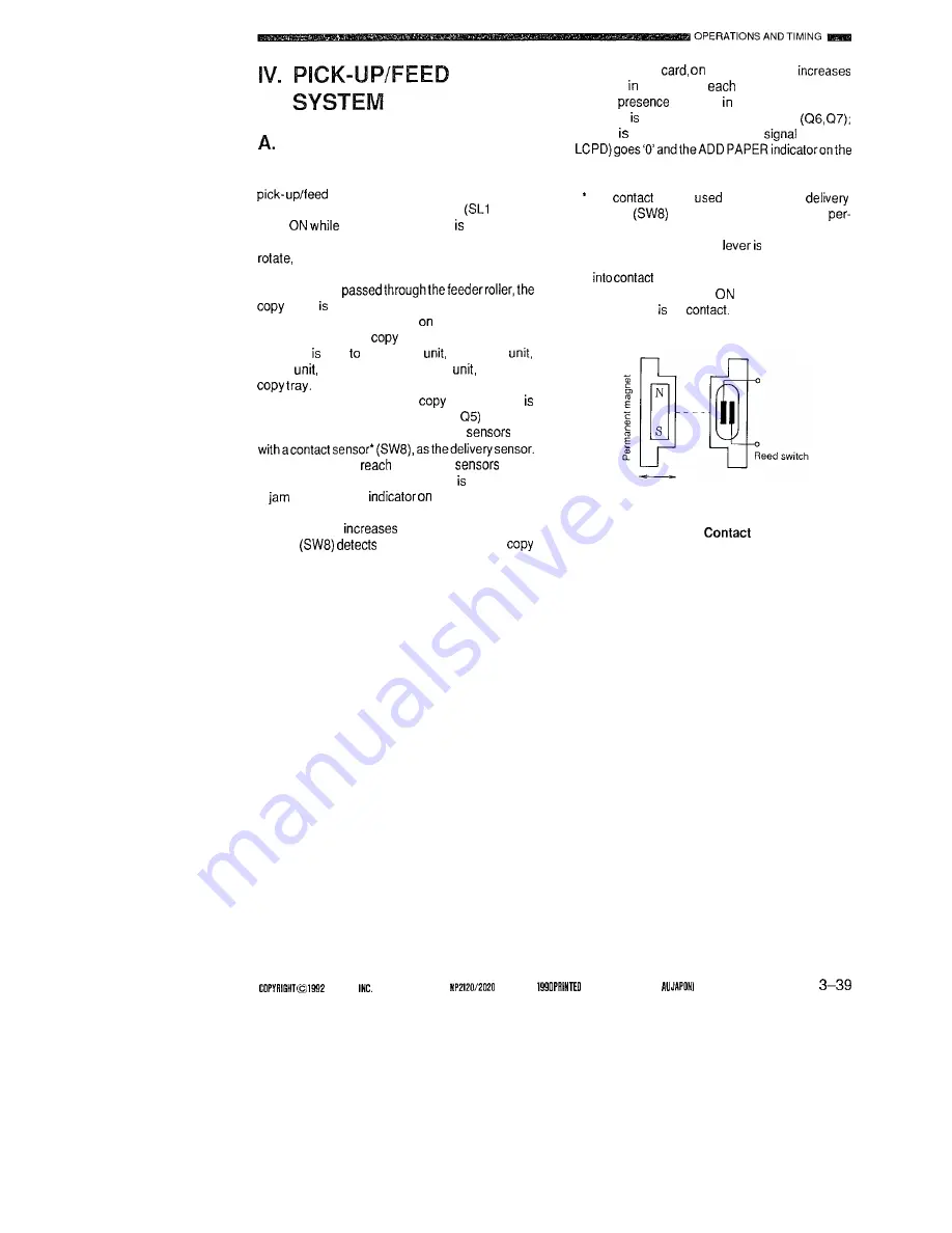
Figure 3-39 shows the basic construction of the
system.
When the pick-up clutch solenoid
or SL2)
goes
the main motor (MI) rotating, the
drive of the main motor causes the pick-up roller to
thereby movingthe paperto feeder roller 1 or
2.
Afterhaving
paper moved by the registration roller so that
the leading edge of the image
the photosensitive
drum and that of the
paper match; thereafter,
the paper sent thetransfer
separation
feeder
fixing assembly, delivery
and to the
The path along which the
paper moves
provided with photointerrupters (Q3,
servicing
as the pre- registration and separation
and
If the paper fails to
or pass the
within
a specific period oftime, thecondition identified as
a
and the JAM
the control panel
starts to flash.
The counter
by one when the delivery
sensor
the trailing edge of the
paper.
The control
the other hand,
the count response to
pick-up.
The
of paper the upper and lower
cassettes checked by photointerrupters
if paper absent, the cassette out
(UPCPD,
control panel starts to flash.
The
sensor
as the copier’s
sensor
makes use of attraction of a
manent magnet to drive the reed switch.
The paper detection
equipped with a
permanent magnet and, when the magnet comes
with the reed switch, the switch goes
OFF; the switch goes
(paper resent) when
the magnet off
Figure 3-38
Sensor
C A N O N
C A N O N
RN.0 MAY
IN JAPAN [IMPRIME
Summary of Contents for NP-2020
Page 5: ......
Page 171: ...LL w I n t 0 m a 9zcr 9zcr ...
Page 172: ...I I i I am w m h I I r l I I B m 0 4 u I m ll ...


