(2/58)
1. LIST OF ERROR DISPLAY
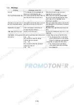
Errors and warnings are displayed by the following ways:
- Operator call errors are indicated by the Alarm LED lit in orange, and the error and its solution
are displayed on the LCD in text and by icon.
- Messages during printing from a computer are displayed on the MP driver Status Monitor.
- Error codes (the latest 10 error codes at the maximum) are printed in the "operator call/service
call error record" area in EEPROM information print.
Buttons valid when an operator call error occurs:
- ON button:
To turn the machine off and on again.
- OK button:
To clear and recover from an error. In some operator call errors, the error will
automatically be cleared when the cause of the error is eliminated, and pressing
the OK button may not be necessary.
- Stop button: To cancel the job at error occurrence, and to clear the error.
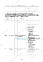
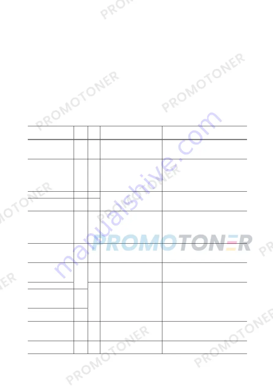
1-1. Operator Call Errors (Alarm LED Lit In Orange)
Error
Error
code
U No.
Message on the LCD
Solution
No paper in the rear
tray.
[1000] --- Rear
tray.
There is no paper. Load
paper and press [OK].
Confirm that the rear tray is selected as
the paper source. Set the paper in the
rear tray, and press the OK button.
No paper in the
cassette.
[1003] --- Cassette.
There is no paper. Load
paper and press [OK].
Confirm that the cassette is selected as
the paper source. Set the paper in the
cassette, and press the OK button.
Note:
Only plain paper can feed from
the cassette.
Paper jam.
[1300] ---
Paper jam in the rear
guide.
[1303] ---
The paper is jammed. Clear
the paper and press [OK].
Remove the jammed paper, and press
the OK button.
Ink may have run
out.
[1600] U041 The following ink may have
run out. Replacing the ink
tank is recommended.
Replace the applicable ink tank, or press
the OK button to clear the error without
ink tank replacement. When the error is
cleared by pressing the OK button, ink
may run out during printing.
Ink tank not installed. [1660] U043 The following ink tank cannot
be recognized.
(Applicable ink tank icon)
Install the applicable ink tank(s) properly,
and confirm that the LED's of all the ink
tanks light red.
Print head not
installed, or not
properly installed.
U051 Print head is not installed.
Install the print head.
Install the print head properly.
Faulty print head ID.
[1401]
Print head
temperature sensor
error.
[1403]
Faulty EEPROM data
of the print head.
[1405]
U052 The type of print head is
incorrect. Install the correct
print head.
Re-set the print head. If the error is not
cleared, the print head may be defective.
Replace the print head.
Multiple ink tanks of
the same color
installed.
[1681] U071 More than one ink tank of the
following color is installed.
Replace the wrong ink tank(s) with the
correct one(s).
Ink tank in a wrong
position.
[1680] U072 Some ink tanks are not
installed in place.
Install the ink tank(s) in the correct
position.
Summary of Contents for MP540
Page 11: ...11 58...
Page 19: ...19 58 7 Remove the main case and sub case 1 screw...
Page 27: ...27 58 3 EXTERNAL VIEW PARTS LIST FIGURE 1 PACKING CONTENTS PRINT HEAD...
Page 29: ...29 58 FIGURE 2 AC ADAPTER...
Page 31: ...31 58 FIGURE 3 EXTERNAL COVERS SCANNER UNIT...
Page 33: ...33 58 FIGURE 4 DOCUMENT PRESSURE PLATE UNIT...
Page 35: ...35 58 FIGURE 5 OPERATION PANEL UNIT...
Page 37: ...37 58 FIGURE 6 MAIN CASE FRONT DOOR UNIT...
Page 39: ...39 58 FIGURE 7 BOTTOM CASE INK ABSORBER...
Page 41: ...41 58 FIGURE 8 LOGIC BOARD ASS Y PE SENSOR BOARD ASS Y...
Page 43: ...43 58 FIGURE 9 SHEET FEED UNIT...
Page 45: ...45 58 FIGURE 10 CARRIAGE UNIT PRESSURE ROLLER UNIT...
Page 47: ...47 58 FIGURE 11 PLATEN UNIT SPUR UNIT...
Page 49: ...49 58 FIGURE 12 PURGE DRIVE SYSTEM UNIT SWITCH SYSTEM UNIT...
Page 51: ...51 58 FIGURE 13 OPTION CONSUMABLES...
Page 53: ...53 58 FIGURE 14 TOOL...
Page 55: ...55 58 REFERENCE PRINTER UNIT...


