background image

(25/34) 

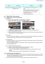
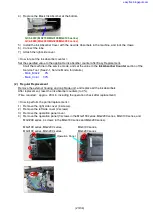
9)  Remove the HS door (2 screws). 


10)  Remove the cap blade unit (4 screws, 2 tubes). 


11)  Release the two claws and tube, then take out the Ink Absorber Cover with the Ink Absorbers fitted in. 


12)  Replace the three sheets of ink absorbers in the bottom unit. 


13)  Replace the ink absorbers in the Ink Absorber Cover to the new ones, and install them in the machine. 

(For replacement procedures, see (1) Easy Replacement, step 3).) 

14)  Install and attach the cap blade unit, HS door, scanner middle frame, and right side cover. 
 

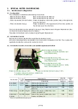
QC3-6072 (MG2100/MG3100/MG4100 series) 

QC4-6099 (MG2200/MG3200/MG4200 series) 

QC3-6073 (MG2100/MG3100/MG4100 series) 

QC4-6098 (MG2200/MG3200/MG4200 series) 

QC3-6074 (MG2100/MG3100/MG4100 series) 

QC4-6100 (MG2200/MG3200/MG4200 series) 

Tube


Ink Absorber Cover + Ink Absorbers


Tube


Tube


easyfixs.blogspot.com

Summary of Contents for MG2100 Series

Page 1: ...G2150 MG2160 MG2170 MG2180 MG3110 MG3120 MG3130 MG3140 MG3150 MG3160 MG3170 MG3180 MG4110 MG4120 MG4130 MG4140 MG4150 MG4160 MG4170 MG4180 MG2210 MG2220 MG2240 MG2250 MG2260 MG2270 MG3210 MG3220 MG323...

Page 2: ...26 2011 All New edition 01 June 1 2012 All 2012 2H models MG2200 series MG3200 series MG4200 series added 02 April 17 2013 8 1 2 Service Call Error revised To the scanner error the scanner unit is add...

Page 3: ...g 18 1 Carriage rail and main chassis adjustment 18 2 Document pressure sheet adjustment 18 3 Cap blade unit ink tube arrangement 19 4 Logic board cable wiring 19 5 Carriage unit FFC arrangement 19 2...

Page 4: ...hat the paper guides are set properly If they are not aligned to the paper edge properly the error can occur Pick up arm unit Paper output cover is open 1202 E06 Paper output cover is open Close the p...

Page 5: ...cartridge or press the Stop button for 5 sec or longer to continue printing without replacing the ink cartridge s When the error is cleared by pressing the Stop button the function to detect the remai...

Page 6: ...G4200 series only 1 2 Service Call Error by Cyclic Blinking of Alarm and Power LEDs Cycles of LED blinking Error Error code 1 Check points Solution Parts to be replaced if the listed solutions are not...

Page 7: ...parts 5 If the error still occurs Replace the part s listed on the right under Parts to be replaced if the listed solutions are not effective Carriage unit Logic board ass y 6 times Internal temperatu...

Page 8: ...the part s listed on the right under Parts to be replaced if the listed solutions are not effective Scanner unit Logic board ass y 26 times Network related error MG3100 series MG3200 series MG4100 se...

Page 9: ...G4200 series i With the machine power turned off while pressing the Stop button press and hold the ON button DO NOT release the buttons ii When the Power LED lights in blue while holding the ON button...

Page 10: ...the paper source Select Cassette and click OK The following EEPROM information items will be printed Model name ROM version Ink absorber counter value Print information Error information etc 3 Nozzle...

Page 11: ...le in most cases of errors 9 Panel Check Button and LCD test See 3 Button and LCD test below 10 Set Destination Destination settings Select the destination and click Set ASA AUS BRA CHN CND EMB EUR JP...

Page 12: ...n the front tray The Service Test Pattern will be printed Printed items Model name ROM version USB serial number Process inspection information Barcode model name destination machine serial number Not...

Page 13: ...disconnected The card board or the FFC is faulty The logic board is faulty Note If the Access lamp does not turn on when a memory card is inserted in the slot it is likely that the memory card itself...

Page 14: ...14 34 Select test item s XXXX00001 Parameter1 Start button Test result easyfixs blogspot com...

Page 15: ...turned off and the Alarm and Wi Fi LED s are turned on Press the OK button twice and confirm that the LED turns off in the following order Wi Fi Alarm 2 Button check Press each button of the operation...

Page 16: ...orber counter value to a new EEPROM after the logic board is replaced in servicing 1 Before replacement of the logic board check the ink absorber counter value in EEPROM information print 2 After repl...

Page 17: ...e front tray 1 min Print head cleaning Perform from the printer driver Maintenance tab or via the machine operation panel If there is a missing portion or white streaks in the nozzle check pattern pri...

Page 18: ...d below confirm that the print quality is proper and the print head is not contacting the paper Confirmation test Using Photo Paper Pro II print an image and confirm that the print quality is proper a...

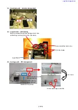
Page 19: ...through the slot Position the FFC with the print side facing up when installed in the printer Turn it over Through the slot to the other side Pass around the hook once Fit in the hooks Pass the cables...

Page 20: ...20 34 2 5 Grease Application One drop of grease 9 to 18 mg easyfixs blogspot com...

Page 21: ...rst Then replace the applicable ink absorber and reset its counter to zero 3 Ink absorber location its counter and available replacement method Ink absorber Counter code Replacement Absorber capacity...

Page 22: ...ion check after replacement Main ink absorber Black 100 replaceable Main ink absorber Color 70 replaceable How to perform the partial replacement 1 Remove the right side cover 4 screws 2 Release the t...

Page 23: ...t Remove the external housing and cap blade unit and replace all the ink absorbers After replacement reset the ink absorber counters to 0 Time required approx 20 min including the operation check afte...

Page 24: ...d 1 connector 6 Remove the power switch unit MG4100 series and MG4200 series only 1 screw 7 Remove the scanner middle frame 3 screws 1 connector 1 claw 8 Unlock the carriage by pressing the lock to th...

Page 25: ...er Cover to the new ones and install them in the machine For replacement procedures see 1 Easy Replacement step 3 14 Install and attach the cap blade unit HS door scanner middle frame and right side c...

Page 26: ...roducts EEPROM information print and the quick reference table refer to Service Information Q 12E J 0188 for details For 2010 1H and later products EEPROM information print Criteria 2 The ink absorber...

Page 27: ...driver Maintenance tab Print the print head alignment pattern and scan the printed pattern Note Scanning of the printed pattern is likely to be omitted Be sure to fully advise users of this 2 Manual p...

Page 28: ...ies only Low Ink warning 1 Printing does not stop Printing may become faint after the message is displayed The dialog box does not pop up Low Ink warning 2 Printing does not stop The same dialog box a...

Page 29: ...MG4200 series U162 Printing stops Pressing the Stop Reset or Stop button for five seconds or longer will disable the function to detect the remaining ink amount and enable printing without replacement...

Page 30: ...ilm Check the encoder film and clean it if it is smeared Errors concerned Error 5100 Vertical streaks or improper shift of the print position dot mis alignment How to check the encoder film If the enc...

Page 31: ...ten a cotton swab with the prepared cleaning water Eliminate extra water so that no water drops 2 Using the moistened cotton swab wipe the encoder film Caution Be cautious so that no water drops insid...

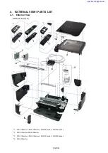
Page 32: ...W PARTS LIST 4 1 External View External View 1 2 1 MG2100series MG3100series MG2200series MG3200series 2 MG4100series MG4200series 3 MG3100series MG4100series MG3200series MG4200series 4 MG4200series...

Page 33: ...33 34 External View 1 2 easyfixs blogspot com...

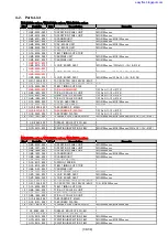
Page 34: ...PLATEN SI No Q11 12J 0132 15 QC4 5950 000 2 ABSORBER PLATEN SI No Q11 12J 0132 16 QK1 7367 000 1 FLEXIBLE FLAT CABLE WLAN MG3100series MG4100series SI No Q11 12J 0140 CK 0562 000 1 GREASE MOLYKOTE PG...

Reviews: