background image

10

CONNECTING THE PROJECTOR

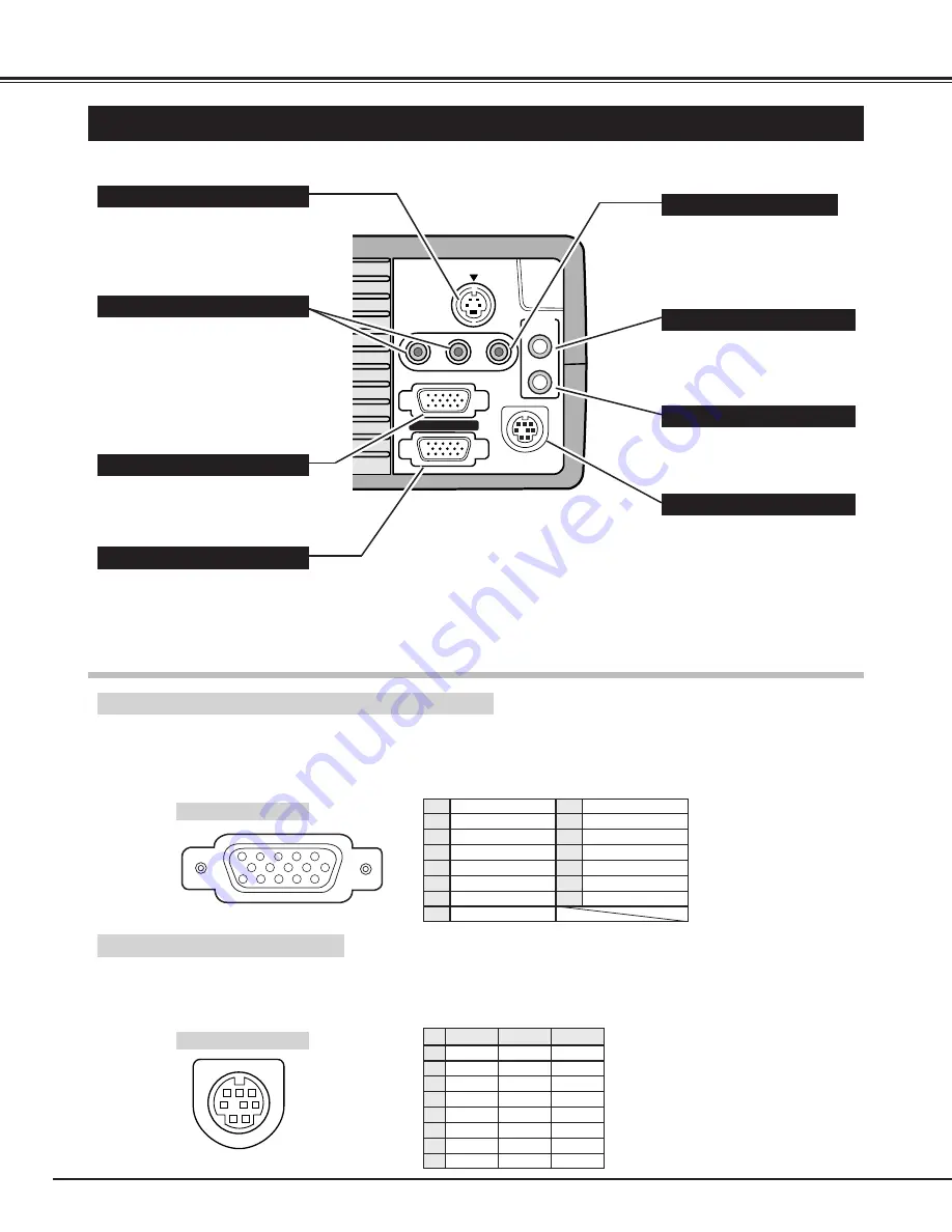
TERMINALS OF THE PROJECTOR

S-VIDEO

R-AUDIO-L

(MONO)

VIDEO

AUDIO

IN

OUT

CONTROL PORT

COMPUTER IN

MONITOR OUT

Connect the computer output to
this terminal.  
(Refer to P12, 13.)

When controlling the computer
with the Remote Control of this
projector, connect the mouse
port of your personal computer
to this terminal.  It is also used
for write on or read from the
data of the PC CARD SLOT in
MCI mode. 
(Refer to P12, 13, 35.)

This terminal outputs the signal
from the COMPUTER IN
terminal.  Connect to a monitor
using this terminal.
(Refer to P12, 13.)

Connect the audio amplifier to
this terminal.
(Refer to P12, 13.)

Connect the S-VIDEO output
from the video equipment to this
terminal.
(Refer to P11.)  

Connect the audio output from
the computer to this terminal.  
(Refer to P12, 13.)

Connect the audio outputs from
the video equipment to these
terminals.
(Refer to P11.)

When the audio output is
monaural, connect it to the L
(mono) jack.

COMPUTER INPUT TERMINAL

MONITOR OUTPUT TERMINAL

CONTROL PORT CONNECTOR

COMPUTER AUDIO INPUT JACK

AUDIO INPUT JACKS

VIDEO INPUT JACK

S-VIDEO INPUT JACK

AUDIO OUTPUT JACK (STEREO)

Connect the video output from
the video equipment to this
terminal.
(Refer to P11.)  

COMPUTER INPUT / MONITOR OUTPUT TERMINAL

Terminal : HDB15-PIN 
Connect the display output terminal of the computer to COMPUTER INPUT with the VGA Cable (supplied).  And connect
the monitor to MONITOR OUTPUT with the monitor cable (not supplied).  When connecting the Macintosh computer, the
MAC Adapter (not supplied) is required.

5

1

2

3

4

10

9

6

7

8

15

14

13

11

12

Red Input

Ground (Horiz.sync.)

Green Input

Sense 2

Blue Input

Ground (Red)

Ground (Green)

Ground (Blue)

1

5

2

4

3

6

7

8

Non Connect

Horiz. sync.

Ground (Vert.sync.)

Sense 1

Sense 0

Vert. sync.

Reserved

9

13

10

12

11

14

15

Pin Configuration

Terminal : Mini DIN 8-PIN
Connect control port (PS/2, Serial or ADB port) on your computer to this terminal with the Control Cable (the Control
Cable for PS/2 port is supplied).

1

2

3

4

5

8

7

6

Pin Configuration

CONTROL PORT CONNECTOR

-----

CLK

DATA

GND

-----

-----

GND

-----

R X D

-----

-----

GND

RTS

T X D

GND

GND

-----

ADB

-----

GND

-----

-----

-----

GND

PS/2

Serial

ADB

1

2

3

4

5

6

7

8

Summary of Contents for LV-7325U

Page 1: ...E English Multimedia Projector Owner s Manual LV 7325U ...

Page 2: ...nter function from the Laser Light Window while pressing the LASER button for 1 minute Do not look into the Laser Light Window or shine the laser beam on yourself or other people Eye damage may result This projector should be set in the way indicated If not It may result in fire hazard If the projector will not be used for an extended time unplug the projector from the power outlet READ AND KEEP T...

Page 3: ...jector yourself as opening or removing covers may expose you to dangerous voltage or other hazards Refer all servicing to qualified service personnel Unplug this projector from wall outlet and refer servicing to qualified service personnel under the following conditions a When the power cord or plug is damaged or frayed b If liquid has been spilled into the projector c If the projector has been ex...

Page 4: ... TO THE VIDEO EQUIPMENT 11 CONNECTING TO THE COMPUTER 12 OPERATION OF THE REMOTE CONTROL 14 LASER POINTER FUNCTION 14 REMOTE CONTROL BATTERY INSTALLATION 15 TOP CONTROLS AND INDICATORS 16 OPERATING ON SCREEN MENU 17 HOW TO OPERATE THE ON SCREEN MENU 17 FLOW OF ON SCREEN MENU 17 MENU BAR 18 BASIC OPERATION 20 TURNING ON OFF THE PROJECTOR 20 ADJUSTING THE IMAGE 21 ZOOM ADJUSTMENT 21 FOCUS ADJUSTMENT...

Page 5: ...rom most personal computers Accessories This projector comes with the parts listed below Check to make sure all are included If any parts are missing contact to a sales dealer Owner s Manual AC Power Cord Wireless Remote Control Unit Batteries for Remote Control Unit VGA Cable Control Cable for PS 2 Port Media Card Imager for Windows 95 CD ROM and Owner s Manual for this software Lens Cover and St...

Page 6: ...ould be taken Do not put a flammable object near this vent Keep heat sensitive objects away from the exhaust vent Do not touch this area especially screws and metallic parts This area will become hot while the projector is used INFRARED REMOTE RECEIVER POWER CORD CONNECTOR EXHAUST VENT FRONT OF THE CABINET LAMP COVER ADJUSTABLE FEET AND FEET LOCK LATCHES PROJECTION LENS SPEAKER Monaural INFRARED R...

Page 7: ...ge can also be adjusted using the Menu Operation Refer to pages 21 29 30 and 37 3 POSITIONING THE PROJECTOR This projector is designed to project on a flat projection surface The projector can be focused from 4 6 1 4m 35 4 10 8m Refer to the figure below to adjust the screen size H1 H2 300 231 200 154 150 115 100 77 40 35 4 10 8m 24 0 7 3m 18 0 5 5m 11 8 3 6m 4 6 1 4m Screen Size W x H mm Height H...

Page 8: ...e power systems having a grounded neutral conductor To reduce the risk of electrical shock do not plug into any other type of power system Consult your authorized dealer or service station if your are not sure of the type of power supply in use Connect the projector with the peripheral equipment before turning the projector on Refer to pages 10 13 for connection CAUTION For safety unplug the AC Po...

Page 9: ...le when moving the Projector When moving the projector replace the lens cover and retract the feet to prevent damage to the lens and the cabinet When this projector is not in use for an extended period replace the Lens Cover retract the Adjustable Feet and cover the unit with the Dust Cover supplied with this projector MOUNTING LENS COVER When moving this projector or when it is not used for an ex...

Page 10: ...PUT TERMINAL MONITOR OUTPUT TERMINAL CONTROL PORT CONNECTOR COMPUTER AUDIO INPUT JACK AUDIO INPUT JACKS VIDEO INPUT JACK S VIDEO INPUT JACK AUDIO OUTPUT JACK STEREO Connect the video output from the video equipment to this terminal Refer to P11 COMPUTER INPUT MONITOR OUTPUT TERMINAL Terminal HDB15 PIN Connect the display output terminal of the computer to COMPUTER INPUT with the VGA Cable supplied...

Page 11: ...f the Projector Use either the VIDEO jack or the S VIDEO jack When the both jacks are connected the S VIDEO jack has priority over the VIDEO jack Video Audio Output S VIDEO Output Audio Input VIDEO CABLE S VIDEO CABLE AUDIO CABLE stereo These cables are not supplied with this projector Cables used for connection NOTE When connecting the cable the power cords of both the projector and the external ...

Page 12: ...port Audio Output Audio Input To each terminal of your computer To the Monitor NOTE When connecting the cable the power cords of both the projector and the external equipment should be disconnected from AC outlet Turn the projector and peripheral equipment on before the computer is switched on MAC Adapter Set the slide switches following the chart on the next page Terminal ADB port Control Cable f...

Page 13: ... ON OFF OFF OFF OFF OFF OFF OFF OFF OFF OFF OFF 1 2 3 4 5 6 OFF OFF ON ON ON ON 21 MODE 1152 x 870 CONTROL PORT AUDIO OUT AUDIO IN MONITOR OUT COMPUTER IN Use one of these Control Cables corresponding with the terminal of your computer Set the switches as shown in the table below depend ing on the RESOLUTION MODE that you want to use before your turn on the projector and computer MAC ADAPTER Not s...

Page 14: ...BUTTON LASER BUTTON Used to operate laser pointer function The laser beam is emitted while pressing this button within 1 minute When using the laser pointer for more than 1 minute release the button and press it again This remote control emits a laser beam as the Laser Pointer from the Laser Light Window When the LASER button is pressed the laser light goes on And when the button is pressed more t...

Page 15: ...tact with the pins in the compartment REMOTE CONTROL BATTERY INSTALLATION 1 2 3 MUTE BUTTON Used to mute sound P22 ZOOM BUTTON Used to adjust zoom P21 FOCUS BUTTON Used to adjust focus P21 NO SHOW BUTTON Used to turn the picture into a black image P22 AUTO IMAGE BUTTON Use to operate AUTO IMAGE function P28 VOLUME BUTTON Used to adjust volume P22 D ZOOM BUTTON Used to turn the projector into DIGIT...

Page 16: ...red when internal projector temperature is too high P42 Used to turn the projector on or off P20 Used to select zoom adjust P21 MODE BUTTON SELECT BUTTON FOCUS BUTTONS NORMAL BUTTON VOLUME BUTTON POINT BUTTONS Used to select input source among Computer Video or MCI P23 30 Used to select focus adjust P21 Used to adjust volume P22 Used to reset to normal picture adjustment preset by factory P27 31 3...

Page 17: ...rol and adjust through ON SCREEN MENU 1 2 3 5 4 You can control and adjust this projector through the ON SCREEN MENU Refer to the following pages to operate each adjustment on the ON SCREEN MENU 1 MOVING THE POINTER 2 SELECT THE ITEM Move the pointer see the NOTE below by pressing POINT button s on the TOP CONTROL or the REMOTE CONTROL Select the item by pressing SELECT button SELECT BUTTON POINT ...

Page 18: ... to select a color system among PAL SECAM NTSC NTSC 4 43 PAL M and PAL N Refer to P30 IMAGE MENU Used to adjust the picture image Color Tint White Balance Contrast Brightness Sharpness Refer to P31 SCREEN MENU Used to set the size of the image either Regular or Wide or to correct the Keystone distortion Refer to P30 MENU BAR IN VIDEO MODE Press MENU BUTTON while in Video mode These icons have the ...

Page 19: ...r to P33 MENU BAR IN MCI MODE Press MENU BUTTON while in MCI mode These icons have the same function as the Computer Mode IMAGE MENU Used to adjust the computer image White Balance Contrast Brightness Refer to P36 POSITION MENU Used to adjust the position of the image Refer to P36 SCREEN MENU Used to adjust the size of the image or to correct the Keystone distortion Refer to P37 ...

Page 20: ...r off The message disappears after 4 seconds TURNING ON OFF THE PROJECTOR When the TEMPERATURE WARNING indicator flashes red the projector is automatically turned off Wait at least 5 minutes before turning the projector on again If the TEMPERATURE WARNING indicator continues to flash follow procedures below 1 Disconnect the AC power cord from the AC outlet 2 Check the air filters for dust accumula...

Page 21: ... button on the Remote Control Unit or select the Keystone on the SCREEN menu Refer to page 29 30 37 The message Keystone is displayed 2 Correct the Keystone distortion by pressing the KEYSTONE button or the POINT UP DOWN button s Press the KEYSTONE button or the POINT UP button to reduce the upper part or the image and press the KEYSTONE button or the POINT DOWN button to reduce the lower part The...

Page 22: ... VOLUME button on the Remote Control Unit to adjust the volume The Volume dialog box appears on the screen for a few seconds The POINT UP or VOLUME button increase the volume and the POINT DOWN or the VOLUME button decrease the volume Press the MUTE button on the Remote Control Unit to mute the sound To restore the sound to its previous level press the MUTE button again or press Volume button s SO...

Page 23: ...ithout any special setting Setting of the Computer System may be required when connecting some computers Note The projector may provide the messages below The projector cannot discriminate or detect the input signal from the computer Adjust and set the computer system manually Refer to page 24 There is no signal input from the computer Make sure the connection of the computer and the projector is ...

Page 24: ...LEFT buttons to select PC ADJUST and press the SELECT button Another dialog box Where to reserve Menu will appear In this dialog box you can store the parameter into the area from Mode 1 to Mode 5 When memorizing the new computer parameter select the Mode with the message of Free by pressing the POINT UP DOWN buttons and the SELECT button To change the parameters of the Mode previously set select ...

Page 25: ...Total dots Adjustment of the horizontal or vertical picture position When the image is not centered on the screen adjust each of those items Horizontal Vertical Adjustment of the clamp level When the image has a dark bar s try this adjustment Clamp Adjustment of the area displayed with this projector Select the resolution at the Display area dialog box or adjust the number at the column of H or V ...

Page 26: ...z XGA 10 1024 x 768 XGA 11 1024 x 768 XGA 12 1024 x 768 Interlace XGA 13 1024 x 768 62 04 77 07 XGA 14 1024 x 768 61 00 75 70 XGA15 1024 x 768 35 522 43 48 46 90 58 20 XGA 8 1024 x 768 47 00 58 30 XGA 9 1024 x 768 Interlace 58 03 72 0 SXGA 1 1152 x 864 SXGA 2 1280 x 1024 63 48 79 35 SXGA 3 1280 x 1024 36 00 43 59 SXGA 4 1280 x 1024 64 20 70 40 SXGA 5 1280 x 1024 62 50 58 60 SXGA 6 1280 x 1024 63 9...

Page 27: ...calls the data previously adjusted Reset Stores the adjusted data in the memory Stored Closes the PICTURE IMAGE ADJUSTMENT Menu Quit Each of the keys operates as follow Fine sync Total dots The normal picture level is preset on this projector at the factory and can be restored anytime you press the NORMAL button located on the Top Control or on the Remote Control Unit The Normal display will be di...

Page 28: ...of the position of the image This item can be adjusted manually Refer to page 28 Fine sync Total dots Position Stores the On Off setting of each item Stored Starts the Auto Image Adjustment Go Closes the AUTO IMAGE ADJUSTMENT Menu Quit PICTURE POSITION ADJUSTMENT The position of the image can be adjusted vertically and horizontally through PICTURE POSITION ADJUSTMENT Press the MENU button and the ...

Page 29: ...de The normal Panning Operation may not function properly if the computer system prepared with the PC Adjust is used NOTE The True and the Digital Zoom cannot be operated when RGB HDTV1035i or HDTV1080i is selected on the SYSTEM MENU P23 and 26 Expand function To expand the image size press the D ZOOM button or the SELECT button The image is magnified by degrees Compress function To compress the i...

Page 30: ...broadcast signal format among PAL SECAM NTSC NTSC 4 43 PAL M or PAL N PAL SECAM NTSC NTSC4 43 PAL M PAL N Move the arrow to the Mode and press the SELECT button PICTURE SCREEN ADJUSTMENT This projector has a picture screen resize function which enables you to display the image in desirable size Press the MENU button and the ON SCREEN MENU will appear Press the POINT LEFT RIGHT buttons to select SC...

Page 31: ...ta previously adjusted Reset Stores the data in the memory Stored Closes the PICTURE IMAGE ADJUSTMENT Menu Quit Normal Press POINT LEFT button to lighten the image and press POINT RIGHT button to deepen the image From 0 to 63 Press POINT LEFT button to increase purple and press POINT RIGHT button to increase green From 0 to 63 Press POINT LEFT button to decrease contrast and press POINT RIGHT butt...

Page 32: ...ps out NOTE Be sure to insert the memory card with the front side facing left of the projector Do not insert the card in the reverse The card may be damaged PC CARD SLOT PC CARD SLOT Front PC with Windows 95 Media Card Imager CD ROM Digital Camera Compact Flash with Adapter not supplied PC Card not supplied UNLOAD Press EJECT button and the memory card pops out NOTE Do not take the card out of the...

Page 33: ...th this projector Refer to CF CARD AND PCMCIA ADAPTER on pages 38 and 39 for operation NOTE Some PCMCIA Adapter or PC Card is not available for this projector and cannot provide the image data In that case use the optional Canon Compact Flash Card and PCMCIA Adapter Media Card Imager Media Card Imager CD ROM is supplied with this projector to edit the image data for projecting Installation of Medi...

Page 34: ... To select Index or Page in the table follow the instructions of INDEX SELECTION and PAGE SELECTION below Index and Page The data edited with Media Card Imager is the Index format consisting of several Pages To project the desirable image select the Index and then select the Page in the Index INDEX SELECTION PAGE SELECTION 1 2 Press the MENU button and the ON SCREEN MENU will appear Press the POIN...

Page 35: ...a in the memory card may be damaged Connect the projector to the Personal Computer with the Control Cable for Serial Port optionally supplied refer to page 12 13 Connect the projector to your computer with the Control Cable for Serial Port optionally supplied Refer to CONNECTING COMPUTER on Page 12 13 Insert the memory card into PC CARD SLOT of the projector And then turn on the projector first an...

Page 36: ...AGE ADJUSTMENT Menu Quit Each of the keys operates as follow Close the PICTURE IMAGE ADJUSTMENT Menu Move the arrow to the item and press POINT RIGHT LEFT button It indicates the level of the item PICTURE POSITION ADJUSTMENT Press the MENU button and the ON SCREEN MENU will appear Press the POINT LEFT RIGHT buttons to select POSITION and press the SELECT button The PICTURE POSITION dialog box will...

Page 37: ...image is magnified by degrees Compress function To compress the image size press the D ZOOM button or the RIGHT CLICK button The size of image is reduced by degrees Panning function To pan the image press POINT UP DOWN LEFT RIGHT buttons Panning function can work only when the image is larger than the screen size To cancel Digital Zoom mode press any button except D ZOOM SELECT RIGHT CLICK POINT P...

Page 38: ...lectric charge It has reached the end of its life Insert the CF card firmly into the PCMCIA adapter aligning the arrows on the CF card and PCMCIA adapter When remove the CF card from the PCMCIA adapter pull it straight out You can use the optional Canon Compact FlashTM Card CF card and its PCMCIA adapter designed for the Canon Digital Camera PowerShot series By inserting the CF card into the PCMCI...

Page 39: ...this problem by placing the CF card in a plastic bag and letting it slowly adjust to temperature changes before removing it from the bag If condensation should occur main tain the CF card at a constant temperature and let the moisture evaporate naturally Store CF cards PCMCIA adapters in the protective case provided Do not use or store CF cards PCMCIA adapter in places subject to the following con...

Page 40: ...ment monitor timer by using this function Refer to page 43 Lamp age SELECTING LANGUAGE Press the MENU button and the ON SCREEN MENU will appear Press POINT LEFT RIGHT buttons to select LANGUAGE and press the SELECT button Another dialog box LANGUAGE Menu will appear Press the POINT DOWN button and a red arrow icon will appear Move the arrow to the language that you want to set and then press the S...

Page 41: ...or a Personal Computer installation of the mouse driver not supplied is required Make sure that the mouse driver is properly installed in your computer And make sure that the mouse port of the computer connected to Control Port is activated OPERATING WIRELESS MOUSE When controlling the pointer of the computer operate the Wireless Mouse with POINT button SELECT button and RIGHT CLICK button on the ...

Page 42: ...ns effectiveness and may result in internal heat build up and adversely affect the life of the projector Clean the Air Filters following the steps below AIR FILTER CARE AND CLEANING Clean the Air Filters with brush or wash out the dust and particles 3 Air filters are clogged with dust particles Clean the air filters by following AIR FILTER CARE AND CLEANING below 1 2 If the TEMPERATURE WARNING Ind...

Page 43: ...cement Monitor Timer when the Lamp Assembly is replaced When the Lamp Replacement Monitor Timer is reset the LAMP REPLACEMENT indicator stops lighting Turn the projector on and press the MENU button and the ON SCREEN MENU will appear Press the POINT LEFT RIGHT buttons to select SETTING and press the SELECT button refer to the page 40 Another dialog box SETTING MENU will appear 1 Press the POINT DO...

Page 44: ...DY indicator will light green again and the projector may be turned on by pressing the power ON OFF button Check the TEMPERATURE WARNING indicator If the indicator flashes red the projector cannot be turned on See TURNING ON OFF THE PROJECTOR section on page 20 Check the Projection Lamp Refer to page 43 Image is out of focus Adjust the focus Make sure the projection screen is at least 4 6 1 4m fro...

Page 45: ...e mouse setting on your computer Turn the projector on before you turn on the computer The image data in memory card isn t displayed Check the memory card is inserted properly into PC CARD SLOT Check a memory card is set properly Check MCI mode is selected Check the image data is recorded in the memory card properly Start the projector again The image data can t be written in read from the memory ...

Page 46: ...g Temperature Storage Temperature Accessories LCD Panel System The specifications are subject to change without notice F 1 7 2 0 lens with f 33 2mm 43 1mm Motor zoom and focus 4 6 35 4 1 4 m 10 8 m 150 W UHP RCA Type x 1 Video Audio R and L and Mini DIN 4 pin S Video x 1 Projection Lens Throw Distance Projection Lamp AV Input Jacks VGA HDB 15 Terminal x 1 Computer Input Jacks Mini DIN 8 pin x 1 VG...

Page 47: ...re optionally supplied When ordering those parts give the name and the Type No of it to the sales dealer Control Cable for Serial Port Type No LV CA26 Control Cable for ADB Port Type No LV CA27 MAC Adapter Type No LV AD02 Canon Digitizer Type No LV DP10 ...

Page 48: ...OFFICE One Canon Plaza Lake Success NY 11042 1198 U S A phone 516 328 5960 CANON U S A INC LOS ANGELES OFFICE 15955 Alton Parkway irvine CA 92718 3616 U S A phone 949 753 4320 CANON CANADA INC 6390 Dixie Road Mississauga Ontario L5T 1P7 Canada phone 905 795 1111 CANON INC 2000 YT1 1311 000 PRINTED IN JAPAN ...

Reviews: