Chapter 3
3-22
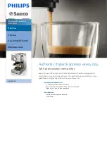
3.2.2.7 Removing the Upper Cover
0010-3753
FAX-L100 / FAX-L120
1) Remove the screw [1].
2) Free the claw [2], and detach the upper cover [3] in the direction of
the arrow.
F-3-106
3.2.2.8 Removing the Reader Unit
0010-3754
FAX-L100 / FAX-L120
1) Disconnect the 3 connectors [1].
2) Remove the screw [2].
3) Free the harness [4] from the clamp [3].
4) Remove the 3 screws [5], and detach the reader unit [5].
F-3-107
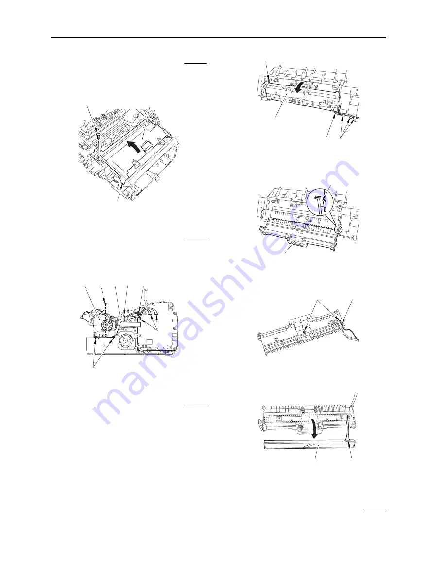
3.2.2.9 Removing the Contact Sensor
0010-3755
FAX-L100 / FAX-L120
1) Free the harness [1] from the cable guide [2].
2) Open the lower reader unit frame [3], and free the claw [4].
F-3-108
3) Free the claw [1], and detach the lower reader unit frame [2].
F-3-109
4) Remove the 2 screws [1], and remove the grounding wire [2].
F-3-110
5) Detach the contact sensor [1] from the lower reader unit frame, and
disconnect the connector [2].
F-3-111
3.2.3 Separation Roller
3.2.3.1 Removing the Right Cover
0010-3779
FAX-L100 / FAX-L120
[1]
[2]
[3]
[1]
[3]
[4]
[5]
[6]
[5]
[2]
[3]
[4]
[1]
[2]
[3]
[4]
[1]
[2]
[1]
[2]
[1]
[2]
Summary of Contents for L100 Series
Page 1: ...Jun 6 2005 Service Manual L100 L120 Series ...
Page 2: ......
Page 6: ......
Page 13: ...Chapter 1 PRODUCT DESCRIPTION ...
Page 14: ......
Page 16: ......
Page 26: ...Chapter 1 1 10 Log on as a user with adoministrator privileges is recommended ...
Page 32: ......
Page 33: ...Chapter 2 TECHNICAL REFERENCE ...
Page 34: ......
Page 36: ......
Page 47: ...Chapter 3 DISASSEMBLY AND ASSEMBLY ...
Page 48: ......
Page 54: ......
Page 111: ...Chapter 4 MAINTENANCE AND INSPECTION ...
Page 112: ......
Page 114: ......
Page 120: ......
Page 121: ...Chapter 5 TROUBLESHOOTING ...
Page 122: ......
Page 124: ...Contents 5 5 5 2 3 Sensor Tests 5 24 5 5 5 2 4 Operation Panel Tests 5 24 ...
Page 150: ......
Page 151: ...Chapter 6 APPENDIX ...
Page 152: ......
Page 154: ......
Page 157: ...Jun 6 2005 ...
Page 158: ......