background image

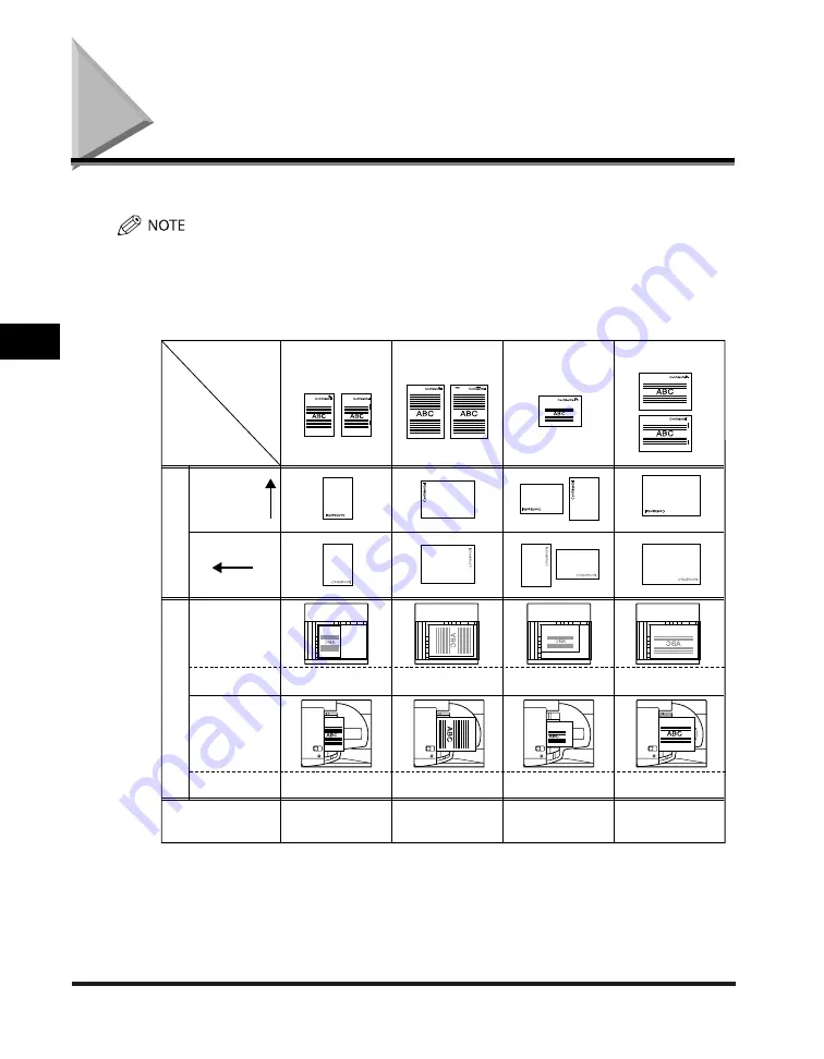
Relationship between Original Orientation and Preprinted Paper Output Chart

4-50

4

Appendix


Relationship between Original Orientation and 
Preprinted Paper Output Chart  

 Please use this chart when printing on preprinted paper (i.e., paper with logos or letterheads). 


 If you want to copy on the back side of preprinted paper, place the side you want to  copy on: 

 face up when using a paper drawer 
 face down when using the stack bypass or the optional Paper Deck-Q1 

 If You Want to Set Right Side Stapling: 


Double: Right

11"x17", LGL, LTRR

Corner: Bottom Right
Double: Right

Output
Example

Staple
Position

Original/
Paper
Orientation,
Settings

Corner: Top Right
Double: Right

Corner: Top Right
Double: Right

Corner: Top Right
Double: Right

Corner: Top Right
Double: Right

Original side:
 Face down

Original side:
 Face up

Preprinted side:
 Face down

Orig

inal

P

reprint

ed P

aper

Preprinted side:
 Face up

LTR

LTR

Corner: Top Right
Double: Top

Corner: Top Right
Double: Right

Corner: Top Right
Double: Right

Corner: Top Right
Double: Right

Corner: Top Right

Corner: Top Right

Corner: Top Right

11"x17", LGL, LTRR

Orientation on
the platen glass

Orientation in
the feeder

Staple position

Staple position

Auto Orientation Setting

Either On or Off

Either On or Off

Either On or Off

Either On or Off (Set to 'On'
when paper orientation in the
paper deck/stack bypass/paper
drawer is vertical.)

Orientation in stack
bypass/paper deck

Orientation in
paper drawer


-
-

Summary of Contents for iR3245

Page 1: ...Please read this guide before operating this product After you finish reading this guide store it in a safe place for future reference Troubleshooting Troubleshooting ENG...

Page 2: ......

Page 3: ...iR3245 iR3235 iR3230 iR3225 Troubleshooting...

Page 4: ...e various functions of the machine Tutorial CD 30 Operations and Settings after the Machine Is Installed Getting Started 30 Quick Reference for Basic Operations Easy Operation Guide 30 Important Notes...

Page 5: ...Print Web Access Network Remote UI MEAP SSO Security Software e Manual 30 To view the manual in PDF format Adobe Reader Adobe Acrobat Reader is required If Adobe Reader Adobe Acrobat Reader is not ins...

Page 6: ...ecifications of the main unit and optional equipment Sample Reports the Relationship between Original Orientation and Preprinted Paper Output Chart and index Considerable effort has been made to ensur...

Page 7: ...sclaimers xix Legal Limitations on the Usage of Your Product and the Use of Images xx Important Safety Instructions xxi Installation xxi Power Supply xxiii Handling xxiv Maintenance and Inspections xx...

Page 8: ...aple Cartridge in the Saddle Stitcher Unit 2 42 Removing Punch Waste 2 46 Replacing the Toner Cartridge 2 49 Routine Cleaning 2 54 Platen Glass and Cover 2 55 Manual Feeder Cleaning 2 56 Automatic Fee...

Page 9: ...nt Log List 4 3 Device Information Delivery Destination List 4 4 Device Information Communication Log Report 4 5 Send Job List 4 6 Send TX Report Send Error TX Report 4 8 Fax TX Report Fax Error TX Re...

Page 10: ...f Various Functions 4 48 Relationship between Original Orientation and Preprinted Paper Output Chart 4 50 Index 4 53 System Management of the iR3245 iR3235 iR3230 iR3225 4 57 Entering the System Manag...

Page 11: ...e observed for safety Indicates a warning concerning operations that may lead to death or injury to persons if not performed correctly To use the machine safely always pay attention to these warnings...

Page 12: ...Kit has been activated and the following optional equipment is attached to the iR3245 the Feeder DADF U1 Super G3 FAX Board UFR II PCL Printer Kit Finisher S1 Additional Finisher Tray B1 and Cassette...

Page 13: ...lowing optional equipment attached to it the Feeder DADF U1 Finisher S1 Additional Finisher Tray B1 and Cassette Feeding Unit Y3 Abbreviations Used in This Manual In this manual product names and mode...

Page 14: ...f Apple Inc registered in the U S and other countries Windows the Windows logo Windows Vista and the Windows Vista logo are trademarks or registered trademarks of Microsoft Corporation in the U S and...

Page 15: ...lex way so that not only copies but also various kinds of prints may sometimes have to wait their turn before they can be printed To avoid confusion when reading this manual the terms scanning printin...

Page 16: ...xiv Printing data scanned from an original followed by finishing options such as stapling Copying...

Page 17: ...230 F152000 iR3225 F152300 EMC Directive This equipment conforms with the essential requirements of EC Directive 89 336 EEC We declare that this product conforms with the EMC requirements of EC Direct...

Page 18: ...d by the equipment s manual Additional Information When servicing or adjusting the optical system of the product be careful not to place screwdrivers or other shiny objects in the path of the laser be...

Page 19: ...er office equipment The program backs the development and dissemination of products with functions that effectively reduce energy consumption It is an open system in which business proprietors can par...

Page 20: ...cts the title ownership and intellectual property rights in and to the SOFTWARE Except as expressly provided herein no license or right expressed or implied is hereby conveyed or granted by Canon s li...

Page 21: ...al on the CD ROM bundled with this product for more detail and corresponding license conditions Disclaimers The information in this document is subject to change without notice CANON INC MAKES NO WARR...

Page 22: ...rint or otherwise reproduce any particular document and or of the use of the images scanned printed or otherwise reproduced you should consult in advance with your legal advisor for guidance Paper Mon...

Page 23: ...covered under your Limited Warranty Installation Do not install the machine near alcohol paint thinner or other flammable substances If flammable substances come into contact with electrical parts in...

Page 24: ...of working parts inside the machine Blocking these openings can cause the machine to overheat Never place the machine on a soft surface such as a sofa or rug Do not install the machine in the followin...

Page 25: ...her than the power cord provided as this may result in a fire or electrical shock As a general rule do not use extension cords Using an extension cord may result in a fire or electrical shock If an ex...

Page 26: ...e Also do not spill water liquids or flammable substances alcohol benzene paint thinner etc inside the machine If these items come into contact with a high voltage area inside the machine it may resul...

Page 27: ...The laser beam can be harmful to human bodies Since radiation emitted inside the product is completely confined within protective housings and external covers the laser beam cannot escape from the ma...

Page 28: ...per or when inspecting the inside of the machine do not allow necklaces bracelets or other metal objects to touch the inside of the machine as this may result in burns or electrical shock Do not burn...

Page 29: ...throw used toner cartridges into open flames as this may cause the toner remaining inside the cartridges to ignite resulting in burns or a fire Do not store toner cartridges or copy paper in places e...

Page 30: ...ges Approximately 3 seconds per page fax transmission time based on CCITT ITU T No 1 Chart JBIG Standard Mode at 33 6 Kbps modem speed The Public Switched Telephone Network PSTN currently supports 28...

Page 31: ...ower is turned OFF before inspecting the breaker If a malfunction occurs after an inspection contact your local authorized Canon dealer Checking the Breaker 1 Push the test button on the rear of the m...

Page 32: ...urn the power ON and OFF If the breaker lever does not switch to the OFF side position repeat step 1 If the breaker lever does not switch to the OFF side position despite carrying out the above proced...

Page 33: ...xxxi 4 Press the main power switch to the I side I side side 5 Fill in the check sheet located on the next page to document your periodic inspections of the breaker...

Page 34: ...the procedure described in Periodic Inspection of the Breaker on p xxix once or twice a month How to Fill in This Check Sheet Fill in the date of inspection and the name of the inspector When the ins...

Page 35: ...and Handling 1 2 Installation Precautions 1 2 Handling Precautions 1 6 Backing Up Data 1 9 Parts and Their Functions 1 10 External View 1 10 Internal View 1 12 Control Panel Parts and Functions 1 13...

Page 36: ...ling the Machine in the Following Locations Avoid locations subject to temperature and humidity extremes whether low or high For example avoid installing the machine near water faucets hot water heate...

Page 37: ...may be more noticeable during extended use or long production runs especially in poorly ventilated rooms It is recommended that the room be appropriately ventilated sufficient to maintain a comfortab...

Page 38: ...e quality of the copied image the inability to properly scan an original or the copies having no printed image at all Avoid installing the machine near computers or other precision electronic equipmen...

Page 39: ...achine s leveling feet are in place Select a Safe Power Supply Plug the machine into a 220 240 V AC outlet Make sure that the power supply for the machine is safe and has a steady voltage Do not conne...

Page 40: ...Moving the Machine If you intend to move the machine even to a location on the same floor of your building contact your local authorized Canon dealer beforehand Do not attempt to move the machine your...

Page 41: ...such as paper clips or staples inside the machine If a foreign object comes into contact with electrical parts inside the machine it might cause a short circuit and result in a fire or electrical shoc...

Page 42: ...y be more noticeable during extended use or long production runs especially in poorly ventilated rooms It is recommended that the room be appropriately ventilated sufficient to maintain a comfortable...

Page 43: ...ice Information Delivery Settings mode You can perform temporary backing up of your data by delivering data registered in the machine to other client machines For information on the Device Information...

Page 44: ...ts on the outside and inside of the main unit control panel and the touch panel display An illustration of the machine with some optional equipment attached to it is also provided For more information...

Page 45: ...g nonstandard paper stock such as envelopes For more information on optional equipment parts and their functions see e Manual Optional Equipment Main Power Switch Press to the I side to turn the power...

Page 46: ...Cover Open this cover to clear a paper jam in the fixing unit See Fixing Unit Inside the Main Unit on p 3 11 Duplexing Unit Pull out the duplexing unit to clear a paper jam See Duplexing Unit Inside...

Page 47: ...nks green when the machine is performing operations and maintains a steady green light when fax data is stored in memory Clear key Press to clear entered values or characters Numeric keys Press to ent...

Page 48: ...rent How to Turn ON the Main Power This section explains how to turn ON the main power 1 Make sure that the power plug is firmly inserted into the power outlet Do not connect or disconnect the power c...

Page 49: ...he screens shown below are displayed while the system software is loading If login authentication by a login service SSO H Single Sign On H is not set and an application other than MEAP is selected as...

Page 50: ...nual Copy Mail Box and Send Fax You can select which functions to display on the Basic Features screen when turning ON the main power according to the Additional Functions settings See e Manual Additi...

Page 51: ...p screen is displayed You can press to switch to the Basic Features screen to use the Copy Mail Box etc functions even if the MEAP Start Up screen is still displayed The MEAP Application screen is dis...

Page 52: ...is installed and you want to be able to send or receive fax documents Sending or receiving I fax or fax documents cannot be done when the main power is turned OFF If SSO H is set as the login service...

Page 53: ...s activated the machine asks you to confirm and cancel any existing jobs and then access to the hard disk is restricted This procedure protects the hard disk from access errors the next time the machi...

Page 54: ...exporting data using the Remote UI function In a rare instance the machine may not go into the Shutdown mode even if you press and hold the control panel power switch for more than three seconds In th...

Page 55: ...the current job is displayed on the first line and the other jobs are processed in the order in which they were reserved up to seven jobs 3 Confirm the message displayed press Yes If There Are Jobs C...

Page 56: ...down a message asking for your confirmation to continue appears on the screen Press Yes However as it is possible that this will destroy data which is being processed or cause damage to the machine it...

Page 57: ...er the machine shuts down the control panel power switch automatically turns OFF and the main power switch of machine automatically switches to the side The machine may continue to operate during or a...

Page 58: ...Main Power and Control Panel Power 1 24 1 Before You Start Using This Machine...

Page 59: ...Envelopes 2 18 Changing Envelope Sizes 2 21 Feeder DADF U1 Optional 2 28 Replacing the Stamp Cartridge 2 28 Finisher S1 Puncher Unit Q1 R1 S1 Optional 2 30 Replacing the Staple Cartridge 2 30 Removing...

Page 60: ...eder Attachment C2 is attached Paper Drawers 3 and 4 can only be used if the optional Cassette Feeding Unit Y3 is attached For more information on available paper stock that can be loaded into the pap...

Page 61: ...ermal transfer printer Do not print on the reverse side of this paper either Fan the stack of paper well before loading it and align the edges of the paper stack on a flat surface Never place paper or...

Page 62: ...Routine Maintenance 1 Press and release the button on the paper drawer in which you want to load paper 2 Grip the handle and pull out the paper drawer until it stops 3 Open a package of paper and rem...

Page 63: ...ets several times and align the edges to facilitate feeding 4 Load the paper stack into the paper drawer Even out the edges of the paper stack Load the paper stack against the right wall of the paper...

Page 64: ...try turning the paper stack over and reload it For more information on the print direction of preprinted paper paper which has logos or patterns already printed on it see Relationship between Origina...

Page 65: ...o a paper drawer follow the procedure described below to adjust the paper drawer guides Only A4 transparencies can be used Make sure that the paper size dial is set to A4 when loading transparencies i...

Page 66: ...e as shown below Without releasing the lever slide the front guide to align it with the mark for the desired paper size Front Guide Adjust the guides correctly to avoid causing a paper jam dirty print...

Page 67: ...paper drawer the wrong paper size will be shown on the touch panel display This may also cause paper jams dirty prints or make the inside of the machine dirty 6 Change the paper drawer s size sticker...

Page 68: ...the control panel power switch to reactivate the machine and then press the open button on the paper deck The paper size of the optional Paper Deck Q1 is fixed to A4 Loading Paper If you select the pa...

Page 69: ...er you load the correct paper If you select another paper source the remaining prints are made after you press OK 1 Press the open button to open the paper deck The inside lifter automatically descend...

Page 70: ...kled paper Thin straw paper Transparencies Paper which has been printed on using a thermal transfer printer Do not print on the reverse side of this paper either For high quality printouts use paper r...

Page 71: ...loaded horizontally If there are instructions on the package of paper about which side of the paper to load follow those instructions When paper is loaded in the paper deck the side facing down is th...

Page 72: ...orcefully move the front guide of the paper drawer in the wrong direction Doing so may detach the envelope feeder attachment from the paper drawer Do not print on both sides of an envelope Doing so ma...

Page 73: ...where the envelopes were stored and the location where the envelopes are being printed leave the envelopes in the printing location at room temperature before you use them Correctly match the paper s...

Page 74: ...ed in the envelope feeder attachment see e Manual Basic Operations Preparing the Envelopes This section explains how to prepare the envelopes before loading them into the paper drawer Using curled cre...

Page 75: ...ection of the arrows to remove any curls Repeat this step five times for each set of five envelopes If you are using ISO B5 ISO C5 COM10 No 10 Monarch Catalog Glove No 8 or DL envelopes hold down the...

Page 76: ...icular care to spread the envelopes out in the direction that they will be fed Do not print on the back side of the envelopes the side with the flap If the envelopes become filled with air flatten the...

Page 77: ...the handle and pull out the paper drawer until it stops 3 Load 10 envelopes at a time with the side you want to print on face up While loading the envelopes press down on the right side of the recepta...

Page 78: ...ght limit mark The maximum height quantity of envelopes that can be loaded into the cassette is approximately 30 mm The maximum height quantity of envelopes varies according to the envelope type and u...

Page 79: ...nt number of envelopes load more envelopes and follow the instructions on the touch panel display Printing resumes Changing Envelope Sizes This section explains how to load different types of envelope...

Page 80: ...tional 2 22 2 Routine Maintenance 3 Pull and lift the paper drawer out of the machine by holding its left and right sides with both hands 4 Remove all of the envelopes that are loaded in the paper dra...

Page 81: ...the appropriate slot for the desired envelope size To remove the left guide tilt the left guide to the right and then pull it up Left Guide 6 Loosen the two screws fixing the front width guide of the...

Page 82: ...n place with the screws 9 Move the back width guide of the envelope feeder attachment in accordance with steps 6 to 8 10 Load 10 envelopes at a time with the side you want to print on face up While lo...

Page 83: ...ch have been rolled or curled must be straightened out prior to use Make sure that the height of the envelope stack does not fall below the height limit mark The maximum height quantity of envelopes t...

Page 84: ...the envelope size and type stored in ENV 1 in Envelope Cassette in Common Settings from the Additional Functions screen to be loaded ENV 2 enables the envelope size and type stored in ENV 2 in Envelop...

Page 85: ...of the paper drawer next to the envelopes Doing so may cause paper jams If output has been stopped due to an insufficient number of envelopes load more envelopes and follow the instructions on the to...

Page 86: ...nger visible When replacing the stamp cartridge take care not to allow ink to come into contact with your hands or clothing If ink gets onto your hands or clothing wash it off immediately with cold wa...

Page 87: ...tweezers Make sure that the stamp cartridge is not protruding from the surface Insert the stamp cartridge properly or paper jams may occur 4 Gently close the inner cover and then close the feeder cov...

Page 88: ...uncher unit may differ according to the regions Replacing the Staple Cartridge When the optional Finisher S1 is almost out of staples and the staple cartridge must be replaced a screen similar to the...

Page 89: ...Open the front cover of the finisher 2 Lift the handle of the finisher unit up and then pull it out to the left Do not place any objects on the finisher unit or lean on it as doing so may damage the...

Page 90: ...he staple case from the stapler unit holding it by the green tab 4 Place the staple case as shown below press the area indicated by PUSH and then pull out the staple cartridge PUSH PUSH 5 Insert the n...

Page 91: ...efore you place the staple cartridge into the staple case Only one staple cartridge can be inserted at a time 6 Remove the seal holding the staples together by pulling it straight out and then down PU...

Page 92: ...o not place your fingers or hands under the finisher as they may get caught resulting in personal injury 9 Close the front cover of the finisher When closing the front cover of the finisher be careful...

Page 93: ...ay of the optional Puncher Unit Q1 R1 S1 becomes full a screen similar to the one shown below appears on the touch panel display Follow the procedure described below to remove the punch waste This pro...

Page 94: ...Finisher S1 Puncher Unit Q1 R1 S1 Optional 2 36 2 Routine Maintenance 2 Pull out the punch waste tray 3 Discard the punch waste Make sure that the punch waste tray is completely emptied...

Page 95: ...te tray to its original position If the punch waste tray is not securely in place you cannot make prints in the Hole Punch mode 5 Close the front cover of the finisher When closing the front cover of...

Page 96: ...e of the puncher unit may differ according to the regions Replacing the Staple Cartridge in the Stapler Unit When the optional Finisher AE1 or Saddle Finisher AE2 is almost out of staples and the stap...

Page 97: ...her Unit L1 M1 N1 Optional 2 39 2 Routine Maintenance 1 Open the front cover of the finisher The Optional Saddle Finisher AE2 The Optional Finisher AE1 2 Lift and pull out the staple case from the sta...

Page 98: ...pull out the staple cartridge PUSH PUSH 4 Insert the new staple cartridge Press the spring loaded case down until it clicks into place PUSH PUSH Use only staple cartridges intended for use with this m...

Page 99: ...enance 5 Remove the seal holding the staples together by pulling it straight out and then down PUSH Make sure that you pull the seal straight out and then down If you pull it out at an angle it may te...

Page 100: ...es ready for stapling after the cover is closed the stapler unit automatically performs a dry stapling operation to reposition the staples Replacing the Staple Cartridge in the Saddle Stitcher Unit Wh...

Page 101: ...artridge in the saddle stitcher unit This procedure is necessary only if the optional Saddle Finisher AE2 is attached We recommend that you order staple cartridges from your local authorized Canon dea...

Page 102: ...e 3 Pull the stapler unit of the saddle stitcher unit towards you and then push it up Stapler Unit of the Saddle Stitcher Unit 4 Pull out the empty staple cartridge holding it by its left and right si...

Page 103: ...tional 2 45 2 Routine Maintenance 6 Pull the stapler unit of the saddle stitcher unit towards you and then push it down into its original position 7 Gently push the saddle stitcher unit back into its...

Page 104: ...staple cartridge be sure to manually reposition the staples in the saddle stitcher unit See e Manual Additional Functions Removing Punch Waste When the punch waste tray of the optional Puncher Unit L...

Page 105: ...r AE2 Puncher Unit L1 M1 N1 Optional 2 47 2 Routine Maintenance 1 Open the front cover of the punch waste tray 2 Pull out the punch waste tray 3 Discard the punch waste Make sure that the punch waste...

Page 106: ...aste tray to its original position If the punch waste tray is not securely in place you cannot make prints in the Hole Punch mode 5 Close the front cover of the punch waste tray When closing the front...

Page 107: ...have it available when needed When toner runs out completely and prints can no longer be made a screen with instructions on how to replace the toner cartridge like the one shown below appears on the...

Page 108: ...clothing wash it off immediately with cold water Washing it off with warm water will set the toner and make it impossible to remove the toner stains Use only toner cartridges intended for use with thi...

Page 109: ...tridge out of the toner supply port Pull the toner cartridge out halfway and then remove it completely while supporting it and keeping it straight with your other hand from underneath Do not burn or t...

Page 110: ...e arrow counterclockwise to remove it Do not touch the tip of the toner cartridge or subject it to shock by hitting it Doing so may cause the toner cartridge to leak 5 Push the new toner cartridge in...

Page 111: ...w on the locking lever is aligned with the right arrow of the Lock icon position If you insert a toner cartridge intended for use in a different machine the locking lever will not move 7 Close the ton...

Page 112: ...bserve these steps may result in a fire or electrical shock Do not use alcohol benzene paint thinner or other solvents for cleaning Doing so may result in damage to the plastic parts Disconnect the po...

Page 113: ...or the underside of the optional platen cover is dirty the original may not be scanned clearly or the size of the original may be detected incorrectly 1 Clean the platen glass and the underside of th...

Page 114: ...lers Do not dampen the cloth too much as this may damage the original or break the machine Spin the rollers while cleaning them This procedure is necessary only if the optional Feeder DADF U1 is attac...

Page 115: ...t tab Inner Cover 4 Clean the rollers a total of three places inside the inner cover with a cloth dampened with water Then wipe the area with a soft dry cloth 5 Clean the transparent plastic part of t...

Page 116: ...inner cover When closing the inner cover be careful not to get your fingers caught as this may result in personal injury 7 Close the feeder cover When closing the feeder cover be careful not to get yo...

Page 117: ...scanning area with a cloth dampened with water Then wipe the area with a soft dry cloth Feeder s Scanning Area 10 While turning the resin roller clean the resing roller and the area around the resin...

Page 118: ...Maintenance 11 Close the feeder When closing the feeder be careful not to get your fingers caught as this may result in personal injury Be aware that the light emitted from the platen glass may be ver...

Page 119: ...ssary only if the optional Feeder DADF U1 is attached It takes approximately 20 seconds to clean the feeder 1 Press Additional Functions Adjustment Cleaning Feeder Cleaning 2 Place 10 sheets of blank...

Page 120: ...recommended for this machine tracing paper labels and other types of paper stock are available For more information contact your local authorized Canon dealer Do not store paper in places exposed to...

Page 121: ...te resulting in burns or a fire Do not store toner cartridges in places exposed to open flames as this may cause the toner to ignite resulting in burns or a fire Keep toner and other consumables out o...

Page 122: ...Consumables 2 64 2 Routine Maintenance...

Page 123: ...r of the Finisher AE1 Saddle Finisher AE2 Optional 3 58 Inside the Buffer Pass Unit E2 of the Finisher AE1 Saddle Finisher AE2 Optional 3 61 Inside the Front Cover of the Saddle Finisher AE2 Optional...

Page 124: ...eces of paper left inside the machine Pulling jammed paper out of the machine by force may leave parts of the paper torn inside leading to frequent paper jams If paper tears while you are trying to re...

Page 125: ...per Jam The location of the paper jam is indicated by a red circle in the upper right corner of the screen If you press Recover Later you can continue operations such as setting modes and scanning ori...

Page 126: ...t with your hands or clothing as this will dirty your hands or clothing If they become dirty wash them immediately with cold water Washing them with warm water will set the toner and make it impossibl...

Page 127: ...am detection of paper jams in the paper drawers is not possible after the power is turned back ON Clear paper jams without turning the power OFF Some areas that are shown to have paper jams may not ac...

Page 128: ...ubleshooting 2 If a paper jam occurs inside an optional unit see the instructions on the following pages Cassette Feeding Unit Y3 See Cassette Feeding Unit Y3 Optional on p 3 29 Paper Deck Q1 See Pape...

Page 129: ...er DADF U1 Optional on p 3 37 Finisher S1 See Finisher S1 Optional on p 3 41 See Finisher S1 Puncher Unit Q1 R1 S1 Optional on p 3 47 See Inside the Transfer Cover of the Finisher S1 Optional on p 3 5...

Page 130: ...Copy Tray J1 See Copy Tray J1 Optional on p 3 77 Finisher AE1 See Inside the Top Cover of the Finisher AE1 Saddle Finisher AE2 Optional on p 3 58 See Inside the Buffer Pass Unit E2 of the Finisher AE...

Page 131: ...op Cover of the Finisher AE1 Saddle Finisher AE2 Optional on p 3 58 See Inside the Buffer Pass Unit E2 of the Finisher AE1 Saddle Finisher AE2 Optional on p 3 61 See Inside the Front Cover of the Sadd...

Page 132: ...e touch panel display Once you have removed all of the jammed paper in locations other than the optional feeder printing or copying resumes If there is paper that still needs to be removed a screen in...

Page 133: ...location of the paper jam and follow the procedure described below and the procedure that appears on the touch panel display to remove the jammed paper The fixing unit and its surroundings inside the...

Page 134: ...ment If the optional Copy Tray J1 is attached to the main unit remove all of the output paper from the tray For more information see e Manual Optional Equipment 2 Pull down the upper cover of the fixi...

Page 135: ...cover of the main unit and then gently close the right cover until it clicks into place in the closed position If the optional Paper Deck Q1 was moved away from the main unit reconnect it to the main...

Page 136: ...Unit If a paper jam occurs inside the duplexing unit a screen similar to the one shown below appears on the touch panel display Check the location of the paper jam and follow the procedure described b...

Page 137: ...Q1 is attached to the main unit move the paper deck away from the main unit before proceeding with this procedure For more information see e Manual Optional Equipment If the optional Copy Tray J1 is...

Page 138: ...reconnect it to the main unit For more information see e Manual Optional Equipment When closing the right cover of the main unit be careful not to get your fingers caught as this may result in person...

Page 139: ...screen similar to the one shown below appears on the touch panel display Check the location of the paper jam and follow the procedure described below and the procedure that appears on the touch panel...

Page 140: ...If the optional Paper Deck Q1 is attached to the main unit move the paper deck away from the main unit before proceeding with this procedure For more information see e Manual Optional Equipment If the...

Page 141: ...er of the main unit and then gently close the right cover until it clicks into place in the closed position If the optional Paper Deck Q1 was moved away from the main unit reconnect it to the main uni...

Page 142: ...aper jam is entirely cleared For more information see Screens Indicating the Locations of Paper Jams on p 3 3 Paper Drawer 1 If a paper jam occurs inside Paper Drawer 1 a screen similar to the one sho...

Page 143: ...Q1 is attached to the main unit move the paper deck away from the main unit before proceeding with this procedure For more information see e Manual Optional Equipment If the optional Copy Tray J1 is...

Page 144: ...Clearing Paper Jams 3 22 3 Troubleshooting 3 Open the paper drawer s right cover 4 Remove any jammed paper 5 Press and release the button on Paper Drawer 1...

Page 145: ...ams 3 23 3 Troubleshooting 6 Grip the handle and pull out the paper drawer until it stops 7 Remove any jammed paper 8 Gently push Paper Drawer 1 back into the machine until it clicks into place in the...

Page 146: ...he paper drawer s right cover be careful not to get your fingers caught as this may result in personal injury 10 Place your hand where the hand symbol is located on the right cover of the main unit an...

Page 147: ...r jam repeatedly appears on the touch panel display until the paper jam is entirely cleared For more information see Screens Indicating the Locations of Paper Jams on p 3 3 Paper Drawer 2 If a paper j...

Page 148: ...cover If the optional Paper Deck Q1 is attached to the main unit move the paper deck away from the main unit before proceeding with this procedure For more information see e Manual Optional Equipment...

Page 149: ...ams 3 27 3 Troubleshooting 4 Grip the handle and pull out the paper drawer until it stops 5 Remove any jammed paper 6 Gently push Paper Drawer 2 back into the machine until it clicks into place in the...

Page 150: ...reconnect it to the main unit For more information see e Manual Optional Equipment When closing the right cover of the paper drawer be careful not to get your fingers caught as this may result in pers...

Page 151: ...inside the machine which are subject to high voltages When removing jammed paper or when inspecting the inside of the machine do not allow necklaces bracelets or other metal objects to touch the insid...

Page 152: ...aper Jams 3 30 3 Troubleshooting 2 Remove any jammed paper 3 Press and release the button on the paper drawer indicated on the touch panel display 4 Grip the handle and pull out the paper drawer until...

Page 153: ...y jammed paper 6 Gently push the paper drawer back into the machine until it clicks into place in the closed position When returning the paper drawer to its original position be careful not to get you...

Page 154: ...tional Equipment When closing the lower right cover of the cassette feeding unit be careful not to get your fingers caught as this may result in personal injury 8 Follow the instructions on the touch...

Page 155: ...on the touch panel display to remove the jammed paper There are some areas inside the machine which are subject to high voltages When removing jammed paper or when inspecting the inside of the machin...

Page 156: ...l down the lever on the side of the paper deck that attaches to the main unit and remove any jammed paper from the feeding area Paper can also be jammed in the feeding slot on the side of the main uni...

Page 157: ...main unit be careful not to get your fingers caught as this may result in personal injury 4 Press the open button to open the paper deck The inside lifter descends automatically If the machine is in...

Page 158: ...paper deck be careful not to get your fingers caught as this may result in personal injury 7 Follow the instructions on the touch panel display The screen indicating the location of the paper jam rep...

Page 159: ...procedure that appears on the touch panel display to remove the jammed paper There are some areas inside the machine which are subject to high voltages When removing jammed paper or when inspecting th...

Page 160: ...Clearing Paper Jams 3 38 3 Troubleshooting 2 Remove any jammed originals 3 Open the inner cover holding it by its front tab Inner Cover 4 Turn the feed dial and remove any jammed originals...

Page 161: ...inner cover When closing the inner cover be careful not to get your fingers caught as this may result in personal injury 6 Close the feeder cover When closing the feeder cover be careful not to get yo...

Page 162: ...ul not to get your fingers caught as this may result in personal injury 9 Follow the instructions on the touch panel display The screen indicating the location of the paper jam repeatedly appears on t...

Page 163: ...the edges of the paper When removing paper which has become jammed inside the machine take care not to cut your hands or injure yourself on the inside of the machine If you cannot remove the paper con...

Page 164: ...Troubleshooting 1 Open the front cover of the finisher If the optional Puncher Unit Q1 R1 S1 R1 S1 is not attached this procedure is not necessary Proceed to step 4 2 Align the pointed notch on the k...

Page 165: ...button on the right cover of the main unit and open the right cover If the optional Paper Deck Q1 is attached to the main unit move the paper deck away from the main unit before proceeding with this...

Page 166: ...the paper output unit 6 Pull down any one of the four inner guides and remove any jammed paper If it is impossible to lower one of the four inner guides try another inner guide Do not attempt to lowe...

Page 167: ...as this may result in personal injury 8 Pull down the upper cover of the fixing unit by its tab and remove any jammed paper If there is difficulty in removing jammed paper from the bottom of the fixi...

Page 168: ...d on the right cover of the main unit and then gently close the right cover until it clicks into place in the closed position If the optional Paper Deck Q1 was moved away from the main unit reconnect...

Page 169: ...s in the optional Finisher S1 and Puncher Unit Q1 R1 S1 a screen similar to the one shown below appears on the touch panel display Check the location of the paper jam and follow the procedure describe...

Page 170: ...ed paper to come into contact with your hands or clothing as this will dirty your hands or clothing If they become dirty wash them immediately with cold water Washing them with warm water will set the...

Page 171: ...the right cover If the optional Paper Deck Q1 is attached to the main unit move the paper deck away from the main unit before proceeding with this procedure For more information see e Manual Optional...

Page 172: ...t cover of the main unit and then gently close the right cover until it clicks into place in the closed position If the optional Paper Deck Q1 was moved away from the main unit reconnect it to the mai...

Page 173: ...out to the left Do not place any objects on the finisher unit or lean on it as doing so may damage the machine or cause the machine to fall over resulting in personal injury 8 Pull down the puncher u...

Page 174: ...then return the finisher unit to its original position When returning the finisher unit to its original position do not place your fingers or hands under the finisher as they may get caught resulting...

Page 175: ...ot to get your fingers caught as this may result in personal injury 13 Follow the instructions on the touch panel display The screen indicating the location of the paper jam repeatedly appears on the...

Page 176: ...are not to cut your hands on the edges of the paper When removing paper which has become jammed inside the machine take care not to cut your hands or injure yourself on the inside of the machine If yo...

Page 177: ...g Paper Jams 3 55 3 Troubleshooting 1 Remove any jammed paper protruding from the output tray 2 Open the front cover of the finisher 3 Lift the handle of the finisher unit up and then pull it out to t...

Page 178: ...oing so may damage the machine or cause the machine to fall over resulting in personal injury 4 Open the transfer cover and then remove any jammed paper Transfer Cover 5 Close the transfer cover When...

Page 179: ...finisher unit to its original position do not place your fingers or hands under the finisher as they may get caught resulting in personal injury 7 Close the front cover of the finisher When closing th...

Page 180: ...r metal objects to touch the inside of the machine as this may result in burns or electrical shock When removing jammed paper take care not to cut your hands on the edges of the paper When removing pa...

Page 181: ...ck if any jammed paper is stuck inside the output area of the finisher If a paper jam occurs when you are printing in the Staple mode do not remove the output sheets that are waiting to be stapled Pri...

Page 182: ...of the finisher be careful not to get your fingers caught as this may result in personal injury 4 Follow the instructions on the touch panel display The screen indicating the location of the paper jam...

Page 183: ...en removing jammed paper take care not to cut your hands on the edges of the paper When removing paper which has become jammed inside the machine take care not to cut your hands or injure yourself on...

Page 184: ...62 3 Troubleshooting 1 Open the buffer pass unit and remove any jammed paper 2 Close the buffer pass unit When closing the buffer pass unit be careful not to get your fingers caught as this may resul...

Page 185: ...occurs inside the front cover of the optional Saddle Finisher AE2 a screen similar to the one shown below appears on the touch panel display Check the location of the paper jam and follow the procedur...

Page 186: ...to allow the toner on the jammed paper to come into contact with your hands or clothing as this will dirty your hands or clothing If they become dirty wash them immediately with cold water Washing the...

Page 187: ...o the upper delivery guide so it returns to its original position when released Upper Delivery Guide 3 Tilt the lower delivery guide to the right and remove any jammed paper Turn the lever on the lowe...

Page 188: ...r of the finisher be careful not to get your fingers caught as this may result in personal injury 6 Follow the instructions on the touch panel display The screen indicating the location of the paper j...

Page 189: ...ot to cut your hands on the edges of the paper When removing paper which has become jammed inside the machine take care not to cut your hands or injure yourself on the inside of the machine If you can...

Page 190: ...8 3 Troubleshooting 1 Open the front cover of the finisher 2 Turn the knob on the right in the direction of the arrow counterclockwise 3 While pushing in the knob on the left turn it in the direction...

Page 191: ...le stitcher unit 5 Tilt the lower delivery guide to the right and remove any jammed paper Turn the lever on the lower delivery guide to the right until it stops and then tilt the lower delivery guide...

Page 192: ...er jam repeatedly appears on the touch panel display until the paper jam is entirely cleared For more information see Screens Indicating the Locations of Paper Jams on p 3 3 Puncher Unit L1 M1 N1 Opti...

Page 193: ...Clearing Paper Jams 3 71 3 Troubleshooting 1 Open the front cover of the punch waste tray 2 Align the pointed notch on the knob within the shaded region 3 Open the top cover of the puncher unit...

Page 194: ...4 Remove any jammed paper 5 Close the top cover of the puncher unit When closing the top cover of the puncher unit be careful not to get your fingers caught as this may result in personal injury 6 Clo...

Page 195: ...er Jams on p 3 3 Inner 2 Way Tray D1 Optional If a paper jam occurs inside the optional Inner 2 Way Tray D1 a screen similar to the one shown below appears on the touch panel display Check the locatio...

Page 196: ...g them with warm water will set the toner and make it impossible to remove the toner stains When removing paper which has become jammed inside the machine remove the jammed paper gently to prevent the...

Page 197: ...he paper output unit 3 Remove any jammed paper 4 Push the paper output unit back into its original position When pushing the paper output unit back into its original position be careful not to get you...

Page 198: ...Q1 was moved away from the main unit reconnect it to the main unit For more information see e Manual Optional Equipment When closing the right cover of the main unit be careful not to get your fingers...

Page 199: ...on the edges of the paper When removing paper which has become jammed inside the machine take care not to cut your hands or injure yourself on the inside of the machine If you cannot remove the paper...

Page 200: ...t and open the right cover If the optional Paper Deck Q1 is attached to the main unit move the paper deck away from the main unit before proceeding with this procedure For more information see e Manua...

Page 201: ...reconnect it to the main unit For more information see e Manual Optional Equipment When closing the right cover of the main unit be careful not to get your fingers caught as this may result in person...

Page 202: ...staple jam occurs in the optional Finisher S1 a screen similar to the one shown below appears on the touch panel display Check the location of the staple jam and follow the procedure described below a...

Page 203: ...of the finisher unit up and then pull it out to the left Do not place any objects on the finisher unit or lean on it as doing so may damage the machine or cause the machine to fall over resulting in p...

Page 204: ...earing Staple Jams 3 82 3 Troubleshooting 4 Push down the tab on the staple case 5 Remove all of the staples that slide from the staple case 6 Return the tab on the staple case to its original positio...

Page 205: ...until it is securely in place 8 Lift the handle of the finisher unit up and then return the finisher unit to its original position When returning the finisher unit to its original position do not pla...

Page 206: ...y stapling operation to reposition the staples Finisher AE1 Saddle Finisher AE2 Optional If a staple jam occurs in the stapler unit of the optional Finisher AE1 or optional Saddle Finisher AE2 a scree...

Page 207: ...leshooting 1 Open the front cover of the finisher The Optional Saddle Finisher AE2 The Optional Finisher AE1 2 Lift and pull out the staple case from the stapler unit holding it by the green tab 3 Pus...

Page 208: ...3 Troubleshooting 4 Remove all of the staples that slide from the staple case 5 Return the tab on the staple case to its original position 6 Gently push the staple case back into the stapler unit unti...

Page 209: ...ared the staple jam be sure to manually reposition the staples in the saddle stitcher unit See e Manual Additional Functions Saddle Stitcher Unit Optional If a staple jam occurs inside the saddle stit...

Page 210: ...klet tray before clearing a staple jam inside the saddle stitcher unit This procedure is necessary only if the optional Saddle Finisher AE2 is attached 1 Open the front cover of the finisher 2 Grip th...

Page 211: ...it of the saddle stitcher unit towards you and then push it up Stapler Unit of the Saddle Stitcher Unit 4 Pull out the staple cartridge containing the jammed staples holding it by its left and right s...

Page 212: ...g 6 Remove any jammed staples and return Part B to its original position B 7 Return the staple cartridge to its original position 8 Pull the stapler unit of the saddle stitcher unit towards you and th...

Page 213: ...ion 10 Close the front cover of the finisher When closing the front cover of the finisher be careful not to get your fingers caught as this may result in personal injury When you have cleared the stap...

Page 214: ...e touch panel display at the following times When scanning or printing cannot be performed because of an operational error When you need to make a decision or take some action during scanning copying...

Page 215: ...page 1 to the top and then press the Start key Data for the scanned original has exceeded limits on the size that can be handled by this machine Automatically adjust settings and try again Cause Scann...

Page 216: ...ace the toner cartridge See Replacing the Toner Cartridge on p 2 49 Place the original on the platen glass Cause The specified mode requires that the original be placed on the platen glass but there i...

Page 217: ...ceive or fax job does not complete successfully the error code is printed in the Results column on the Activity Report and Send Report However if a send job is canceled STOP is printed in the Results...

Page 218: ...Remedy Set Allow Printer Jobs with Unknown IDs to Off See e Manual Security 703 Cause 1 The hard disk is full and no more images can be scanned Remedy 1 Wait a few moments and try scanning again afte...

Page 219: ...e You cannot print because the set page limit total has been reached Remedy Contact your System Manager 817 Cause A communication error occurred between your machine and a remote copy printer Remedy C...

Page 220: ...a job Remedy Try delivering device information again after the client machine finishes processing the job 850 Cause Device information could not be delivered because a screen relating to the delivere...

Page 221: ...to the machine Remedy 2 Try printing again Cause 3 The spool memory is full when Use Spooler in Network Settings in System Settings from the Additional Functions screen is set to On therefore data rec...

Page 222: ...y Contact your local authorized Canon dealer 856 Cause The job was canceled because there was not enough free space on the hard disk to store the temporary data Remedy Contact your System Manager 857...

Page 223: ...er 862 Cause 1 The saddle finisher trays have exceeded their stacking limits Remedy Change the print data or print settings and try printing again Cause 2 A combination of settings which is not suppor...

Page 224: ...functions In addition each function is guaranteed to be able to store the following number of pages Copy 100 pages Print 100 pages excluding Secured Print Jobs For example the Copy function can store...

Page 225: ...scan the remaining originals No The pages scanned into memory are not printed Another Function Select to use another function that is not being used If the desired function is not displayed press or...

Page 226: ...cel The current job is canceled and the display returns to the Basic Features screen Scan the job again when the current job is complete Another Function Select to use another function that is not bei...

Page 227: ...ne shown below appears follow the procedure described below Do not connect or disconnect the power cord with wet hands as this may result in electrical shock Always grasp the power plug when disconnec...

Page 228: ...urning the main power switch back to the I side I side side 3 If the machine still does not operate normally follow the procedure below and then contact your local authorized Canon dealer Turn the mai...

Page 229: ...the finishing modes However after the Limited Functions Mode is deactivated the Service Call Message screen may appear again unless the cause of the malfunction is removed If you shutdown the machine...

Page 230: ...back ON appears 3 Press Shutdown After the machine shuts down the control power switch automatically turns OFF and the main power switch of machine automatically switches to OFF side 4 Wait at least 1...

Page 231: ...oth turned ON always check that the breaker is not in the OFF position If the breaker is in the OFF position contact your local authorized Canon dealer without turning the breaker back ON ON I side OF...

Page 232: ...3 110 3 Troubleshooting Printer Fax Driver Troubleshooting See the Troubleshooting in the driver help to resolve problems when using the printer driver or fax driver for Windows In this section scree...

Page 233: ...Unit Y3 4 30 Paper Deck Q1 4 31 Envelope Feeder Attachment C2 4 31 Finisher S1 4 32 Finisher AE1 4 33 Saddle Finisher AE2 4 34 Puncher Unit L1 M1 N1 4 36 Puncher Unit Q1 R1 S1 4 37 Additional Finisher...

Page 234: ...See e Manual What This Machine Can Do DEPT ID If a Department ID is set it is listed at the top of the log Copy logs are printed for each Department ID JOB NO Prints the four digit number which is aut...

Page 235: ...ints OK or NG OK is printed when the copy job completes successfully NG No Good is printed if an error occurs during the copy job The error code or STOP is also printed next to NG Print Log List The p...

Page 236: ...n the print job completes successfully NG No Good is printed if an error occurs during the print job The error code or STOP is also printed next to NG Device Information Delivery Destination List The...

Page 237: ...tional Functions screen are set for the destination Device Information Communication Log Report The Device Information Communication Log Report contains information about device information that has b...

Page 238: ...The Send Job List can be printed from the System Monitor screen See e Manual Send Fax If the optional Color Universal Send Kit is activated a list of e mail I fax and file server transmissions is pri...

Page 239: ...matically assigned when the document is accepted for sending is printed MODE The type and mode of transmission are printed Transmission type Send TX Mode of transmission FTP SMB IPX WebDAV User Inbox...

Page 240: ...Image is set to On the contents of the sent document are not printed on the report if the document was sent using the Encrypted PDF mode If the optional fax board is installed the results of fax and...

Page 241: ...ield exceeds its display capacity only those characters that fit in the display are printed Fax TX Report Fax Error TX Report This report indicates items such as the fax number of the party to which y...

Page 242: ...on is printed up to the first 20 digits PSWD SUBADDRESS A subaddress is printed if specified The password is not printed to maintain security DESTINATION ID The name of the remote party is printed ST...

Page 243: ...nual Send Fax JOB NO The four digit number that is automatically assigned when the document is accepted for sending is printed DEPT ID If Department ID Management is set the Department ID is printed P...

Page 244: ...optional fax board is installed MESSAGE A message describing the reception result is printed JOB NO The four digit number that is automatically assigned when the document is accepted for receiving is...

Page 245: ...on error occurred NG No Good is printed If a reception error occurred the page number in which the error occurred and the error code number are printed Confidential Fax Inbox RX Report This report ena...

Page 246: ...TION ID The name of the sender is printed ST TIME Start Time The date and time in 24 hour notation at which the document started to be received are printed USAGE T The time taken in minutes and second...

Page 247: ...reached The send and receive logs can also be printed separately An Activity Report can be printed manually at any time from the System Monitor screen See e Manual Send Fax If the optional Color Univ...

Page 248: ...r sending a fax the destination address is printed on the second line DESTINATION ID The name of the recipient is printed JOB NO The four digit number that is automatically assigned when the document...

Page 249: ...lder was actually delivered is printed If a field exceeds its display capacity only those characters that fit in the display are printed Fax Activity Report The Fax Activity Report is a printed log th...

Page 250: ...The name and fax number of the remote party are printed If a subaddress or sender s name has been specified it is printed beneath the fax number NO The four digit number that is automatically assigne...

Page 251: ...the recipient OK is printed If a sending error occurred the page number in which the error occurred and the error code number are printed Forwarding Conditions List You can print the contents of the...

Page 252: ...Sample Reports 4 20 4 Appendix Registered LDAP Server List You can print the registered LDAP server settings See e Manual Send Fax...

Page 253: ...olor Universal Send Kit is activated the details of e mail I fax file server and group destinations are printed If the optional fax board is installed the details of fax and group destinations are pri...

Page 254: ...printed If the Class is I FAX or MAIL The I fax address or e mail address is printed If the Class is FAX The fax number is printed on the first line and the subaddress on the second line if it is spec...

Page 255: ...ta List The User s Data List prints out the Send Settings made in Communications Settings Report Settings and System Settings from the Additional Functions screen Manually print the User s Data List w...

Page 256: ...Sample Reports 4 24 4 Appendix...

Page 257: ...Usage 220 Registered Service com canon meap service portalservice PortalService MEAP Contents 00 73 MEAP Specifications 5 6 7 9 10 11 MEAP Contents Prints the MEAP version MEAP Specifications Prints i...

Page 258: ...stalled on Prints the date and time the application was installed Vendor Prints the name of the application vendor License Status Prints the license status Installed An effective license has been inst...

Page 259: ...s its value the current counter value is not printed Maximum Memory Usage Prints the maximum amount of memory that can be used by each application The Maximum Memory Usage number is printed in kilobyt...

Page 260: ...Type Plain Recycled Color Pre punched Bond Paper Heavy Tracing Paper Transparency Labels Envelopes The printing conditions may vary depending on the paper type For more information see e Manual Basic...

Page 261: ...depending on the number of copies Margin Top Left and Right Bottom 2 5 mm 2 5 mm 2 5 mm Magnification Regular paper size Same Ratio 1 1 Reduction 1 0 86 A3 B4 A4 B5 1 0 81 B4 A4R B5 A5R 1 0 70 A3 A4R...

Page 262: ...depends on the region of purchase Installation Space W x D 862 mm x 700 mm when the stack bypass is extended Feeder DADF U1 Item Specification Original Feeding Mechanism Automatic Document Feeder Siz...

Page 263: ...Space W x D 937 mm x 700 mm Envelope Feeder Attachment C2 Item Specifications Acceptable Envelopes COM10 No 10 Monarch Catalog Glove No 8 DL ISO B5 ISO C5 Yougata 4 Capacity 50 sheets or 30 mm in heig...

Page 264: ...1 000 sheets 30 sets or 130 mm in height A3 B4 A4R 500 sheets 30 sets or 65 mm in height No Collating Collate Group mode with different paper sizes 500 sheets or 65 mm in height Staple mode with diff...

Page 265: ...aper Size Weight Type Size A3 B4 A4 A4R B5 B5R A5R Free size 99 mm x 148 mm to 297 mm x 432 mm Envelopes COM10 No 10 Monarch Catalog Glove No 8 DL ISO B5 ISO C5 Yougata 4 Weight 64 to 128 g m2 Type Pl...

Page 266: ...hen the auxiliary tray is extended Approximately 43 2 kg Installation Space W x D 1 508 mm x 700 mm when the stack bypass and the auxiliary tray are extended 1 615 mm x 700 mm when the optional Punche...

Page 267: ...izes 500 sheets 30 sets or 73 5 mm in height Saddle Stitch mode 1 to 5 sheets 25 sets 6 to 10 sheets 15 sets 11 to 15 sheets 10 sets The maximum number of sets that can fit in the Booklet tray is 10 i...

Page 268: ...re extended Puncher Unit L1 M1 N1 Item Specifications Paper Size Weight Type Size A3 B4 A4 A4R B5 B5R Weight 64 to 128 g m2 Type Plain Recycled Color Heavy Bond Paper Punch Hole Quantity Hole Diameter...

Page 269: ...1 S1 Two Holes 70 mm Three Holes 108 mm Puncher Unit R1 Punch Waste Tray Capacity Approximately 2 500 sheets 64 g m2 Power Source From the optional Finisher S1 Dimensions H x W x D Weight 175 mm x 505...

Page 270: ...e Size A3 B4 A4 A4R B5 A5R Free size 99 mm x 148 mm to 297 mm x 432 mm Envelopes COM10 No 10 Monarch Catalog Glove No 8 DL ISO B5 ISO C5 Yougata 4 Weight 64 to 128 g m2 Type Plain Recycled Color Pre p...

Page 271: ...Specifications 4 39 4 Appendix Item Specification Dimensions H x W x D Weight 120 mm x 347 mm x 351 mm Approximately 471 g Installation Space W x D 912 mm x 700 mm...

Page 272: ...0 dpi 400 x 400 dpi 600 x 600 dpi System Environment Windows XP Vista Windows 2000 Server Professional SP1 or later Windows Server 2003 Novell Netware 3 2 4 11 4 2 5 5 1 Solaris Version 2 6 or later M...

Page 273: ...4 A4 A4R B5 B5R A5 A5R I Fax A3 2 B4 2 A4 A4R B5 3 B5R 4 A5 4 A5R 4 Server Software Microsoft Exchange Server 5 5 SP1 or later Sendmail 8 93 Lotus Domino R 4 6 or later Other Searches a destination vi...

Page 274: ...Transmission Speed Super G3 33 6 kbps G3 14 4 kbps Compression Method MH MR MMR JBIG Transmission Type Super G3 G3 Sending Original Sizes A3 B4 A4 A4R B5 B5R A5 A5R Sent as B4 Sent as A4 Receiving Pa...

Page 275: ...alk Frame type Print application Ethernet SNAP PAP Printer Access Protocol 1 IPv6 is not supported Printer Settings Software Specifications Command Language PCL5e PCL PostScript 3 emulation and UFR II...

Page 276: ...tricted operation No option is attached 1 158 mm 1 035 mm 100 mm or more The optional Feeder DADF U1 Finisher S1 and Paper Deck Q1 are attached 1 087 mm 1 553 mm 100 mm or more The optional Feeder DAD...

Page 277: ...nt 32 characters maximum Device Information Settings Device Name 32 characters maximum Location 32 characters maximum Communications Settings E mail I Fax Settings Default Subject 40 characters maximu...

Page 278: ...ers maximum Fax Name 24 characters maximum One touch Button Name 12 characters maximum Fax Number 120 digits maximum Subaddress 20 digits maximum Password 20 digits maximum File Name 24 characters max...

Page 279: ...er Name 10 characters maximum Mail Box Functions Document Name 24 characters maximum Mode Memory Register Name 10 characters maximum Color Balance Register Name 10 characters maximum Sending Functions...

Page 280: ...Communications Settings Memory RX Inbox Settings Memory RX Inbox Password 7 digits Date Time Settings Year Month day hour Mail Box Settings User Inbox Number of Inboxes 100 Password 7 digits Confiden...

Page 281: ...20 jobs Mail Box Functions Color Balance Number of Keys 4 Mode Memory Number of Keys 9 Reserving Print Jobs Number of Jobs 32 jobs Sending Documents Number of Documents 32 documents maximum Number of...

Page 282: ...er Orientation Settings Corner Top Right Double Right Corner Top Right Double Right Corner Top Right Double Right Corner Top Right Double Right Original side Face down Original side Face up Preprinted...

Page 283: ...le Right Corner Top Left Double Left Original Preprinted Paper Original side Face down Original side Face up Preprinted side Face down Preprinted side Face up Orientation on the platen glass Orientati...

Page 284: ...rinted side Face down Preprinted side Face up Orientation on the platen glass Orientation in the feeder Auto Orientation Setting Orientation in stack bypass paper deck Orientation in paper drawer Orig...

Page 285: ...Control panel power switch 1 13 1 14 1 19 Copying definition xiii Copy log list 4 2 Copyright xviii Copy Tray J1 Clearing Paper Jams 3 77 Specifications 4 38 Counter check key 1 13 D Display contrast...

Page 286: ...2 Screens indicating locations of paper jams 3 3 Parts and functions of the main unit Control Panel 1 13 External view 1 10 Internal view 1 12 Power supply xxiii 1 5 Printer Fax Driver Troubleshootin...

Page 287: ...Q1 4 31 Printer Settings 4 43 Puncher Unit L1 4 36 Puncher Unit Q1 4 37 Saddle Finisher AE2 4 34 Super G3 FAX 4 42 Stack bypass About the stack bypass 1 11 Clearing paper jams 3 17 Start key 1 13 Sto...

Page 288: ...Index 4 56 4 Appendix...

Page 289: ...ings stored by other users The operations which can be performed in the System Management mode are Managing documents in an inbox Managing Mail Box Settings Entering the System Management Mode If you...

Page 290: ...4 Appendix If Department ID Management Is Enabled 1 Enter the System Manager ID and System Password using numeric keys Press Dept ID enter the System Manager ID Press Password enter the System Passwo...

Page 291: ...System Management of the iR3245 iR3235 iR3230 iR3225 4 59 4 Appendix If Department ID Management Is Not Enabled 1 Press Additional Functions...

Page 292: ...System Management of the iR3245 iR3235 iR3230 iR3225 4 60 4 Appendix 2 Press System Settings...

Page 293: ...Press System Manager ID enter the System Manager ID Press System Password enter the System Password Press Log In Out The System Management mode is enabled Make sure to enter the System Manager ID and...

Page 294: ...the iR3245 iR3235 iR3230 iR3225 4 62 4 Appendix Canceling the System Management Mode 1 Press Log In Out The System Management mode is canceled The System Management mode is also canceled when the Auto...

Page 295: ...nager can access documents in inboxes that have been stored by other users For example you can access an inbox whose user has forgotten his her password and erase any unnecessary documents 1 Enter the...

Page 296: ...System Management of the iR3245 iR3235 iR3230 iR3225 4 64 4 Appendix 2 Press Mail Box 3 Operate the Mail Box function For instructions on using the Mail Box function see e Manual Mail Box...

Page 297: ...t is not being used or change the name of an inbox You can also reset the password of an inbox if the user has forgotten it 1 Enter the System Management mode For instructions on entering the System M...

Page 298: ...System Management of the iR3245 iR3235 iR3230 iR3225 4 66 4 Appendix...

Page 299: ......

Page 300: ...r regional dealer CANON LATIN AMERICA INC 703 Waterford Way Suite 400 Miami Florida 33126 U S A CANON AUSTRALIA PTY LTD 1 Thomas Holt Drive North Ryde Sydney N S W 2113 Australia CANON CHINA CO LTD 15...

Reviews: