


Chapter 4
4-26
8) Remove the original size sensor (Vertical scan direction) [1] together with
them mount.
- Screws [2] 3 pcs.
F-4-59
9) Remove the original size sensor (Vertical scan direction) [1].
- Connectors [2] 2 pcs.
F-4-60
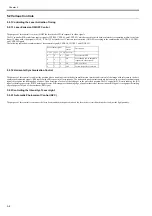
4.4.7.2 Removing the Original Sensor (Horizontal Scan
Direction) (When the original size detection sensor is
equipped for BOOK mode)
0020-4406
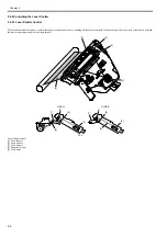
1)Open the copyboard glass cover or ADF.
2) Remove the copyboard glass.
3) Remove the cover [1].
- Screw [2] 1 pc.
F-4-61
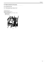
4) Remove the connector [1] from the reader controller PCB, and then re-
move the harness from the edge saddle [2].
5) Remove the original size sensor (horizontal scan direction) [3] together
with them mount.
- Screws [4] 2 pcs.
F-4-62
6) Remove the harness from the edge saddle/clamp [1], and then disconnect
the connector.
7) Remove the original size sensor [2].
F-4-63
4.4.8 Reader Heater (option)
4.4.8.1 Removing the Reader Heater (Right)
0020-4408
1) Open the copyboard cover (or ADF).
2) Remove the copyboard glass.
3) Remove the heater cover [1].
- Screw [2] 1 pc.
F-4-64
[2]
[1]
[1]
[2]
[2]
[1]
MEMO:
Illustrations of this procedure are figured the document size sensor equipped
model, but procedure is same as document size sensors are not equipped
model.
[3]
[1]
[2]
[4]
[1]
[2]
[2]
[1]
Summary of Contents for iR2422 series
Page 1: ...May 12 2014 Service Manual iR2422 2420 2320 2318 Series...
Page 2: ......
Page 6: ......
Page 16: ...Contents...
Page 17: ...Chapter 1 Introduction...
Page 18: ......
Page 20: ......
Page 50: ......
Page 51: ...Chapter 2 Installation...
Page 52: ......
Page 54: ......
Page 58: ...Chapter 2 2 4 7 Left cover front 15 Right cover upper 8 Manual feed tray 16 Right cover lower...
Page 62: ...Chapter 2 2 8 8 Manual feed tray 16 Right cover lower...
Page 64: ...Chapter 2 2 10 8 Manual feed tray 16 Right cover lower...
Page 89: ...Chapter 2 2 35...
Page 90: ......
Page 91: ...Chapter 3 Main Controller...
Page 92: ......
Page 94: ......
Page 102: ......
Page 103: ...Chapter 4 Original Exposure System...
Page 104: ......
Page 135: ...9 Remove the reader heater left 1 Connector 2 1 pc Screw 3 1 pc F 4 73 2 3 1...
Page 136: ......
Page 137: ...Chapter 5 Laser Exposure...
Page 138: ......
Page 140: ......
Page 148: ...Chapter 5 5 8...
Page 149: ...Chapter 6 Image Formation...
Page 150: ......
Page 152: ......
Page 165: ...Chapter 7 Pickup Feeding System...
Page 166: ......
Page 192: ...Chapter 7 7 24...
Page 193: ...Chapter 8 Fixing System...
Page 194: ......
Page 196: ......
Page 207: ...Chapter 9 External and Controls...
Page 208: ......
Page 229: ...Chapter 10 Maintenance and Inspection...
Page 230: ......
Page 232: ......
Page 235: ...Chapter 11 Standards and Adjustments...
Page 236: ......
Page 238: ......
Page 240: ...Chapter 11 11 2...
Page 241: ...Chapter 12 Correcting Faulty Images...
Page 242: ......
Page 244: ......
Page 256: ......
Page 257: ...Chapter 13 Self Diagnosis...
Page 258: ......
Page 260: ......
Page 269: ...Chapter 14 Service Mode...
Page 270: ......
Page 272: ......
Page 287: ...Chapter 15 Upgrading...
Page 288: ......
Page 290: ......
Page 295: ...Chapter 16 Service Tools...
Page 296: ......
Page 298: ......
Page 300: ......
Page 301: ...Chapter 17 Backup Data...
Page 302: ......
Page 303: ...Contents Contents 17 1 Backup Data 17 1...
Page 304: ......
Page 306: ......
Page 307: ...May 12 2014...
Page 308: ......


