9
9
9-102
9-102
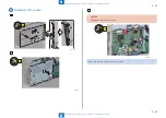
Installation > Serial Intreface KIT-K2/ Copy Control Interface KIT-A1 > Installation Outline Drawing
Installation > Serial Intreface KIT-K2/ Copy Control Interface KIT-A1 > Installation Outline Drawing
Serial Intreface KIT-K2/ Copy Control Interface
KIT-A1
Points to Note at Installation
• Refer to "Table of Options Combination" when installing this equipment before operation.’
• Serial Interface Kit and Control Interface Kit cannot be used concurrently.
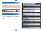
Table of Options Combination
Utility
Tray
V
oice Operation Kit
V
oice Operation Kit
Serial Interface Kit
Copy Control
Interface Kit
Copy Card Reader
Serial Interface
Kit
yes
yes
yes
-
no
no
Copy Control
Interface Kit
yes
yes
yes
no
-
no
yes: Available no: Unavailable
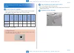
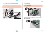
CAUTION: Marked portion
When tightening the screws, do not tighten them too tightly. Otherwise, there is a risk
of damage and deformation of screw holes.
F-9-250
T-9-9
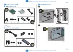
Check that the main power switch is OFF
1) Turn OFF the main power switch of the host machine.
2) Be sure that Control Panel Display and Main Power Lamp are both turned OFF, and then
disconnect the power plug.
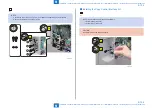
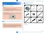
Installation Outline Drawing
F-9-251


