Canon imageRUNNER 2520 Service Manual Download Page 95

2

2

2-67

2-67

Technology > Pickup Feed System > Controls > Multi-Purpose Pickup Assembly

Technology > Pickup Feed System > Controls > Multi-Purpose Pickup Assembly

Paper level sensor

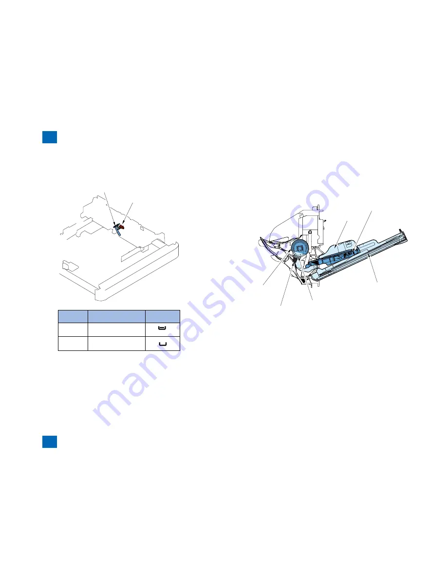
This machine does not have the paper level sensor in the cassette.
This machine has the cassette 1 paper sensor (S2) to detect the paper.

Cassette 1 Paper Sensor (S2)

Flag

Cassette 

paper sensor

Paper level

Display

OFF

paper presence

ON

paper absent

F-2-95

F-2-95

T-2-38

T-2-38

Multi-Purpose Pickup Assembly

Overview

The paper in the tray of the manual feed pickup unit is forced against the manual feed pickup 

roller by the work of the pickup guide plate, and only a single sheet
of paper is separated and moved into the machine by the work of the manual feed pickup 

roller and the separation pad.

Side guide

Pickup guide plate

Manual feed pickup tray

Separation pad

Pressure spring

Manual feed 

pickup roller

Paper Presence Detection

The paper presence is detected by the Multi-Purpose Tray Paper Presence Sensor.

When the paper absence is detected, if there is the same size & same type paper exists in 
other cassette, auto cassette change is executed.

Paper Size Detection

This machine does not have the paper size detection detection function. The user must set 

the size of the paper in the multi manual feed tray using the operation panel, or the user must 
register a fixed size in the user mode.Image masking area is regulated based on the result of 
paper width detection so that the image to be reproduced does not beyond the paper width.

F-2-96

F-2-96

Summary of Contents for imageRUNNER 2520

Page 1: ...9 8 7 6 5 4 3 2 1 imageRUNNER 2530 2525 2520 Series Service Manual ...

Page 2: ...nformation as the need arises In the event of major changes in the contents of this manual over a long or short period Canon will issue a new edition of this manual The following paragraph does not apply to any countries where such provisions are inconsistent with local law Trademarks The product names and company names used in this manual are the registered trademarks of the individual companies ...

Page 3: ...wer switch closing the front door and closing the delivery unit door which results in supplying the machine with power 2 In the digital circuits 1 is used to indicate that the voltage level of a given signal is High while 0 is used to indicate Low The voltage value however differs from circuit to circuit In addition the asterisk as in DRMD indicates that the DRMD signal goes on when 0 In practical...

Page 4: ...Blank Page ...

Page 5: ...peration 1 12 Power Switch 1 12 Description of Control Panel 1 12 2 Technology Basic Configuration 2 2 Functional Configuration 2 2 Basic sequence 2 2 Original Exposure System 2 3 Construction 2 3 Specifications controls functions 2 3 Major Components 2 3 Reader relay PCB 2 4 Basic Sequence 2 5 Basic Sequence at Power On 2 5 Basic Sequence at Start Key ON book mode 1 original 2 5 Basic Sequence at...

Page 6: ... initial rotation 2 36 Sequence of Operation printing 2 36 Sequence of Operation last rotation 2 36 Controls 2 37 Drum Unit 2 37 Developing Unit 2 38 Toner Container 2 39 Transfer Unit 2 40 Waste Toner Box 2 41 Work of Service 2 42 When Replacing the Components 2 42 Periodical Service 2 42 Points to Note about Service 2 42 Fixing System 2 43 Overview 2 43 Features 2 43 Specifications 2 43 Major pa...

Page 7: ... Removing the Left Rear Cover 4 18 Removing the Toner Supply Cover 4 18 Removing the Reader Right Cover 4 19 Removing the Platen Glass 4 19 Removing the Reader Rear Cover 4 19 Removing the Rear Cover Right 4 20 Removing the Rear Cover Left 4 21 Removing the Rear Right Cover Upper 4 21 Removing the Rear Right Cover Lower 4 21 Removing the Lower Rear Cover 4 21 Removing the Cassette 2 Rear Cover 4 2...

Page 8: ...rts 5 2 Image position adjustment 5 2 Adjustment when replacing parts 5 3 Scanning System 5 3 Action to Take after Replacing the CIS Unit 5 3 Action to Take after Replacing the Platen Glass 5 3 Action to Take after Replacing the ADF Scan Glass 5 4 Controller System 5 4 Action to Take after Replacing theMain Controller PCB 5 4 Action to Take when Replacing the DC Controller PCB 5 4 Action to Take a...

Page 9: ...y of the transmitted license 8 36 Erasing a License 8 37 E RDS 8 38 Configuration 8 38 REPORT 8 39 Configuration 8 39 Details 8 39 DOWNLOAD 8 43 Download 8 43 CLEAR 8 44 Configuration 8 44 DISPLAY 8 44 Configuration 8 44 ROM 8 45 Configuration 8 45 TEST MODE 8 45 Outline 8 45 Configuration 8 45 Details 8 46 9 Installation How to check this Installation Procedure 9 2 When Using the parts included i...

Page 10: ...nstallation 9 42 Turning OFF the Host Machine 9 42 Installation Procedure 9 43 Checking after Installation 9 43 Cst Heater Kit J1 Installation Procedure 9 44 Checking the Contents 9 44 Points to Note Before Installation 9 44 Turning Main Power OFF 9 44 Installation Procedure 9 45 Reader Heater Unit H1 Installation Procedure 9 52 Checking the Contents 9 52 Points to Note Before Installation 9 52 Tu...

Page 11: ...3 7 V General Circuit Diagram 4 7 VI General Circuit Diagram 5 7 VII General Circuit Diagram 6 7 VIII General Circuit Diagram 7 7 IX General Circuit Diagram 250 sheet 1st cassette type X General Circuit Diagram 1 7 X General Circuit Diagram 2 7 XI General Circuit Diagram 3 7 XII General Circuit Diagram 4 7 XIII General Circuit Diagram 5 7 XIV General Circuit Diagram 6 7 XV General Circuit Diagram ...

Page 12: ...g of Laser System Turn power switch ON Points to Note About Turning Off the Main Power Switch Safety of Toner Notes When Handling a Lithium Battery Notes Before it Works Serving Safety Precautions imageRUNNER 2530 2525 2520 Series ...

Page 13: ...UFACTURED 30 2 SHIMOMARUKO 3 CHOME OHTA KU TOKYO JAPAN THIS PRODUCT CONHORMS WITH DHHS RADIATION PERFORMANCE STANDARD 21CFR CHAPTER 1 SUBCHAPTER J A different description may be used for a different product Laser Safety When servicing the area around the laser assembly be sure to turn off the main power The machine s covers that can reflect laser light are identified by means of a warning label Fi...

Page 14: ...h Control panel power switch F 0 3 F 0 3 Power Supply 1 As a general rule do not use extension cords Using an extension cord may result in a fire or electrical shock If an extension cord must be used however use one for local rated voltage and over untie the cord binding and insert the power plug completely into the extension cord outlet to ensure a firm connection between the power cord and the e...

Page 15: ...cause the toner to jell and fuse permanently with the fibers of the cloth Tonner is easy to react with plastic material avoid contact with plastic Notes When Handling the Lithium and Ni MH Batteries RISK OF EXPLOSION IF BATTERY IS REPLACED BY AN INCORRECT TYPE DISPOSE OF USED BATTERIES ACCORDING TO THE INSTRUCTIONS The following warnings are given to comply with Safety Principles EN60950 Wenn mit ...

Page 16: ...1 1 Product Overview Product Overview Product Lineup Feature Specifications Name of Parts ...

Page 17: ...e configuration Host machine configuration Reader DADF standard or optional Printer Model type imageRUNNER 2530 imageRUNNER 2525 imageRUNNER 2520 Print Speed 30ppm 25ppm 20ppm Positioning Target machine imageRUNNER 2025 2022 2018 Series imageRUNNER 2530 2525 2520 Underlined 2 digit numeric figures indicate print speed ppm print per minute T 1 1 T 1 1 T 1 2 T 1 2 F 1 2 F 1 2 ...

Page 18: ...it U1 is required 6 Reader Heater Unit H1 Cst Heater Kit J1 is required 7 Platen Cover Type P 8 Document Tray J1 9 FL Cassette AJ1 10 FL Cassette AK1 11 FL Cassette AL1 12 Cassette Heater Unit 37 Cst Heater Kit J1 is required 13 Cassette Module W1 Cassette Spacer A1 is required when installing to 250 Sheets Cassette Model 14 CST Feeding Unit AE1 Cassette Spacer A1 is required when installing to 25...

Page 19: ...t Interface Kit A1 5 Serial Interface Kit J2 6 System Upgrade RAM C1 7 System Upgrade SD Card A1 8 Copy Control Interface Cable A1 9 Barcode Printing Kit B1 PCL Printer Kit AF1 is required 10 PCL Printer Kit AF1 System Upgrade RAM C1 is required 11 PS Printer Kit AF1 System Upgrade RAM C1 is required 12 Color Send Kit Y1 System Upgrade RAM C1 is required 13 Color Send Searchable PDF Kit C1 System ...

Page 20: ...loping unit Highly durable OPC drum is adopted High image quality High speed support Laser scanner unit Capable of 1200 dpi Waste toner container User replaceable Low running cost High image quality Low running cost Fixing film Stainless steel is adopted for the heatsink to improve efficiency of heat radiation F 1 5 F 1 5 ...

Page 21: ...2 3 hole punch Envelopes No 10 COM10 ISO B5 Monarch ISO C5 DL The optional Envelope Feeder Attachment D1 is required Item Specifications Paper type Manual feed pickup tray Weight 64 g m2 to 128 g m2 Type Plain Recycled Color 64 g m2 to 80 g m2 3 hole punch Bond 75 g m2 to 90 g m2 Heavy Paper 1 81 g m2 to 90 g m2 Heavy Paper 2 91 g m2 to 105 g m2 Heavy Paper 3 106 g m2 to 128 g m2 Transparencies La...

Page 22: ...77 5 kg Min with the platen cover and single cassette Approx 50 5 kg T 1 5 T 1 5 Weight Size Product name Width mm Depth mm Height mm Weight Approx kg imageRUNNER 2530i 2530 2525i 2525 with the platen cover 565 680 806 50 5 with the single cassette imageRUNNER 2530i 2530 2525i 2525 with the feeder 565 693 896 77 5 with the double cassette and 2 way unit imageRUNNER 2520i 2520 with the platen cover...

Page 23: ...14 14 14 Heavy Paper 91 105 106 128 2 sided without the 2 way unit Plain paper 64 90 9 9 9 9 9 9 Heavy Paper 91 105 106 128 T 1 7 T 1 7 Paper type For free size paper refer to the table below Type Feeding direction mm Width direction mm Free size 148 to 432 99 to 297 Pickup Usable paper types are shown Paper type g m2 Size Manual feed pickup tray Cassette 1 Cassette 2 Cassette 3 Cassette 4 with th...

Page 24: ...upply cover 3 Reader front cover 17 Reader right cover 4 Control panel 18 Platen glass 5 Support cover 19 Reader rear cover 6 Delivery tray 20 Rear cover right 7 Front cover 21 Rear cover left 8 Cassette 1 22 Right cover upper rear 9 Cassette 2 standard or optional 23 Right cover lower rear 10 Cassette 3 option 24 Manual feed pickup tray 11 Cassette 4 option 25 Right cover 12 Lower left cover 26 L...

Page 25: ...ual feed pickup roller 3 Platen glass 18 Pickup roller cassette 1 4 Toner bottle 19 Vertical path roller 1 5 Drum unit 20 Feed roller cassette 1 6 Drum cleaning unit 21 Separation roller cassette 1 7 Delivery roller 22 Vertical path roller 2 8 2 way unit 23 Feed roller cassette 2 9 Fixing outlet roller 24 Separation roller cassette 2 10 Fixing film unit 25 Pickup roller cassette 2 11 Pressure roll...

Page 26: ...ADF reading glass 16 Registration roller 3 Platen glass 17 Manual feed pickup roller 4 Toner bottle 18 Pickup roller cassette 1 5 Drum unit 19 Vertical path roller 1 6 Drum cleaning unit 20 Vertical path roller 2 7 Delivery roller 21 Feed roller cassette 2 8 2 way unit 22 Separation roller cassette 2 9 Fixing outlet roller 23 Pickup roller cassette 2 10 Fixing film unit 24 Primary charging roller ...

Page 27: ...o note To turn off the power turn off the Main power Switch Conventional shutdown sequence operation is not required After power off After the Main power Switch is turned off do not reactivate the Main power Switch until a screen disappears do not turn off the power while download is processing F 1 9 F 1 9 Description of Control Panel Control Panel 1 2 3 4 5 6 7 8 9 10 11 12 15 16 13 14 17 18 1 To...

Page 28: ...r Fax Send or Fax Scan Scan or Direct print System Monitor System Monitor Settings Registration menu 6 7 8 9 1 2 3 4 5 1 Common Settings 6 Copy Settings 2 Timer Settings 7 Communications Settings 3 Adjustment Cleaning 8 Printer Settings 4 Report Settings 9 Address Book Settings 5 System Settings T 1 10 T 1 10 T 1 11 T 1 11 F 1 11 F 1 11 Difference of Settings Registration menu imageRUNNER 2030 202...

Page 29: ...2 2 Technology Technology Basic Configuration Original Expusure System Controller System Laser Exposure System Image Formation System Fixing System Pickup Feed System E RDS ...

Page 30: ...exposure system Main controller DC controller Option board Controller system Duplexing feed Delivery Transfer Pickup Fixing Fixing system Image formation system Pickup feed system Laser exposure system Cassette 2 Cassette 1 Laser scanner unit F 2 1 F 2 1 Basic sequence Sequence at Power On Reader Backwarding Main power switch ON SREADY STBY Scanner motor LED CIS HP sensor Shading position Shading ...

Page 31: ...e Main scanning direction by reflection sensor AB INCH Sub scanning direction by reflection sensor AB INCH In ADF mode Main scanning direction by photo interrupter on DADF Sub scanning direction by photo interrupter on DADF 1 Controls differ depending on magnifications Refer to Magnifications for more information T 2 1 T 2 1 Major Components Following shows major components of document exposure sy...

Page 32: ...printer unit J552 Communication with main controller PCB J553 Communication with main controller PCB J554 Communication with main controller PCB J555 Connection to copyboard cover open close sensor and CCD HP sensor J556 Connected to the contact image sensor CIS HP sensor J557 Connection to original size sensor 2A 2B 3 J558 Connected to the contact image sensor CIS sensor J559 Connection to Scanne...

Page 33: ...n Leading edge of original 1 CIS position check CISHP sensor HP F 2 6 F 2 6 F 2 7 F 2 7 Basic Sequence at Start Key ON book mode 1 original Backward movement Forward movement Start key ON SCRW SCFW STBY STBY Scanner motor M31 LED CISHP sensor S31 Black shading White shading Leading edge of original Shading position Shading position Trailing edge of original Original glass reading start position 1 ...

Page 34: ...ce at Start Key ON ADF mode 1 original Backward movement Forward movement Black shading White shading Start key ON SCFW SCRW STBY STBY Scanner motor M31 LED CISHP sensor S31 Stream reading position Trailing edge of original Shading position Shading position Shading position Stream reading start position 1 Black shading White shading Original scan CS HP sensor HP Original glass reading start positi...

Page 35: ...ay PCB PCB2 Scanner motor M31 drive signal Turns on off the motor and controls its direction speed of rotation Contact image sensor CIS HP sensor S31 signal Detects that the contact image sensor CIS is at the home position Copyboard cover open closed sensor front S32 rear S33 detection signal Detects the open close status of the copyboard cover F 2 12 F 2 12 Scanner Motor Control Scanner motor dri...

Page 36: ...pon detection of the trailing edge the motor decelerates rapidly and stops Deceleration 2 Backward Movement after Image Scan After image scan the carriage moves back to the contact image sensor CIS shading position at the constant speed 123 mm sec F 2 14 F 2 14 Contact Image Sensor CIS Outline The original is exposed to light and read using the contact image sensor CIS to read the image on a line ...

Page 37: ...ation Change in Vertical Scan Direction In the Book mode or when the ADF is used In the vertical scan direction the image is read at 100 Magnification is changed by processing data on the main controller PCB Magnification Change in Horizontal Scan Direction In the horizontal scan direction magnification is changed as follows depending on the selected magnification rate 1 When magnification is redu...

Page 38: ...e sensor does not change when the copyboard cover is open close This machine is provided with the following sensors Locations of the sensors are shown below Vertical scan direction Reflection type photo sensors 2 locations for AB 1 location for Inch Horizontal scan direction Reflection type photo sensors 2 locations for AB 2 locations for Inch B5 A4R A4 STMT R LTR R LTR 11 17 LGL B5R Index plate O...

Page 39: ...more than 5 deg but less than 30 deg Original sensor Turns on and original size identification process 2 is performed 5 Original sensor 1 Original sensor 0 Original A4R Original sensor 2A 3 Original sensor 0 1 Original sensor 3 Original sensor 2A 5 The original cover is closed at an angle of 5 deg or less The original size is identified Original sensor Turns off In identifying the original size th...

Page 40: ...riginal sensor 2B Original sensor 3 No original Change absent 1 For Chinese paper the following sizes are detected 8K Equivalent to B4 size 16K Equivalent to B5 size F 2 23 F 2 23 Dirt Sensor Control Overview The machine changes the original read position or corrects the read image depending on the presence absence of dust on the stream reading glass or ADF platen roller thus preventing dust from ...

Page 41: ...is performed once 3 CIS moves to the position C and dust detection is performed once 4 a CIS moves to the position where there is no dust with priority for the detecting position A B C 4 b If dust is detected at all points A B and C move back to position A and the original is scanned at position A A B C F 2 25 F 2 25 Immediately before scanning one sheet at a time The contact image sensor CIS does...

Page 42: ...ller F 2 26 F 2 26 Functions of the image processing system are summarized below Reader relay PCB CMOS sensor drive analog image processing A D conversion and shading correction The reader relay PCB is used to process images on a line by line basis Its major functions are as follows 1 Analog image processing CMOS sensor drive CMOS sensor output gain correction and offset correction CMOS sensor out...

Page 43: ...F 2 28 F 2 28 Shading Correction Outline The CMOS sensor outputs are necessary even for the following reasons even when the density of the original is uniform 1 Variation in sensitivity among CMOS sensor pixels 2 Variation in light intensity of rod lens array The machine performs shading correction to even out the CMOS sensor output There are two types of shading correction shading adjustment perf...

Page 44: ...evel automatic adjustment ADF white level adjustment This action is applicable only when the DFDA is installed in the host machine Refer to page 5 3 Platen glass White plate data adjustment Platen board cover white level automatic adjustment ADF white level adjustment This action is applicable only when the DFDA is installed in the host machine Refer to page 5 3 Stream reading glass Platen board c...

Page 45: ... control reader unit input image processing card reader interface image processing for FAX USB extension hub interface Image memory SO DIMM Temporary saving of image data Capacity 256MB maximum 512 MB Flash ROM Stores system software Boot ROM 16 MB Program ROM 128 MB SRAM Stores user data service data information USB port USB2 0 device I F USB2 0 host I F Ethernet port Ethernet I F SD card slot SD...

Page 46: ...or J8114 Control panel connector J8115 SOFT counter board connector J8116 SOFT ID board connector J8117 Control card connector J8118 Serial interface connector J8119 Card reader connector J8124 Secondary battery unit connector J8125 Power supply connector J8127 NCU board connector J8134 Pseudo CI connector F 2 31 F 2 31 Connector No Function J8140 Serial interface connector J8142 Laser scanner uni...

Page 47: ...L Print PC Original Copy A A A Print output Scan Image data Other iR machine F 2 32 F 2 32 Construction of the Image Processing Module Main controller PCB Processes image data for output to the printer unit Printer unit output image processing block DC controller PCB Reader relay PCB SO DIMM image memory program temporary storage Processes the image data read by the reader unit Reader unit input i...

Page 48: ...ession expansion editing block Edge emphasis Enlargement reduction intensify to density conversion density adjustment F adjustment gamma correction Main controller PCB Reader unit F 2 34 F 2 34 Compressio Extesion Editing Block Main controller PCB to printer unit output image processing block Enlargement reduction Rotation Integration Compression Expansion Reader image processing block PDL image p...

Page 49: ...age Processing Main controller PCB To DC controller PCB Compression expansion editing block Binary density conversion Enlargement reduction Smoothing F 2 36 F 2 36 Flow of Image Data According to Copy Functions Main controller PCB Image processing block for printer unit Image processing block for reader unit Reader unit Data compression Data rotation Data expansion SO DIMM DC controller PCB F 2 37...

Page 50: ...age processing block for reader unit Reader unit Main controller PCB Data rotation Data expansion Resolution conversion SO DIMM USB2 0 To network compression data Ethernet port F 2 38 F 2 38 Flow of Image Data for the Fax Transmission Image processing block for reader unit Image processing block for FAX Super G3 Fax Board Main controller PCB Data rotation Data compression Data expansion SO DIMM Re...

Page 51: ...unction Image processing block for printer unit Image processing block for fax Super G3 Fax Board Main controller PCB Data compression Data rotation Data expansion SO DIMM DC controller PCB F 2 40 F 2 40 Flow of Image Data for the PDL Function Rendering processing block Compression expansion editing block Processing block for printer unit DC controller PCB Main controller PCB SO DIMM Ethernet PDL ...

Page 52: ...or S7 2nd delivery tray No 2 delivery sensor S42 Inner finisher Inner finisher inlet sensor S1 Fan Overview Fan layout FAN6 FAN3 FAN4 T 2 9 T 2 9 F 2 42 F 2 42 No Name Function Error code FAN3 Exhaust fan rear Cools the fixing unit E805 0000 E805 0001 FAN4 Exhaust fan front Cools the fixing unit E805 0002 E805 0003 FAN6 Power supply cooling fan Cools the power supply E804 0000 E804 0001 PTINT LSTR...

Page 53: ...m heater Reader heater Cassette heater Fixing heater 24V 5VR 24VR 5VC USB HUB Kit Interlock switch SW2 24VR 24VU 24VR 24VR Reader relay PCB ADF CIS Main controller PCB DC controller PCB 24VR 5VR 24VR 5VC 24VU 24VR 24VS 5VR 3 3V 5VC 3 3V 5VR Regulator 3 3V 3 3V 5VC Modem PCB VH PCB HVT PCB Laser scanner unit 5VC 12VR No 2 deleivery unit 5VR 3 3V 3 3V 24VR 24VR 24VR Cassette pedestal Inner finisher ...

Page 54: ...The machine is operating or ready to start operating with all power supplies provided Energy saving mode Only the LCD backlight for the control panel is turned off The machine enters this mode when auto sleep timer is activated in the user mode or the energy saving key is pressed Sleep 1 The controller is powered but the engine is not powered Sleep 2 The controller is not powered The sleep 2 mode ...

Page 55: ...leep mode ON ON ON T 2 11 T 2 11 Service Operations Action to take when replacing parts Part name Action Reference Secondary battery The secondary battery is powered even after the main power switch is turned off 1 Press the SW3 on the main controller 2 The LED10 on the main controller goes out 3 Now you can replace parts Refer to page 4 41 SO DIMM Main controller PCB Print the set loaded data Ins...

Page 56: ...32000rpm 1 speed control Type of bearing Oil Polygon mirror The number of face 6 Φ40 Controls Synchronous control Main scanning direction synchronous control Laser intensity control APC control Others Laser ON OFF control Laser scanner motor control Laser shutter control T 2 13 T 2 13 T 2 14 T 2 14 T 2 15 T 2 15 T 2 16 T 2 16 Main Configuration Parts 1 2 4 3 Name Function 1 Laser Unit Emits laser ...

Page 57: ...BD signal Main Controller PCB Image signal Laser control signal Scanner motor control signal F 2 47 F 2 47 Signal name Function Image signal DATA C C laser image data signal entry DATA C C laser image data signal entry DATA D D laser image data signal entry DATA D D laser image data signal entry Laser control signal CTRL0 0 C D laser control signal CTRL0 1 C D laser control signal CTRL0 2 C D lase...

Page 58: ...turns on the laser unit Thereafter when the Start key is turned on themachine generates the image request signal PVREQ on the printer side and turns on the laser beam withreference to the generated signal In the case of A4 1 sheet 1 The BD signal is generated in reference to the light from laser C The BD sensor of the BD PCB receives light from laser C but not light from laser D PRINT STBY STBY IN...

Page 59: ...N For APC control 0 1 1 OFF OFF J8142 CTRL0_2 CTRL0_1 CTRL0_0 Main Controller PCB T 2 19 T 2 19 F 2 49 F 2 49 Main Scanning Synchronous Control The synchronous control in the main scanning direction is performed in the synch circuit based on the BD synchsignal Using the BD signal generated based on the light from laser C the DC controller PCB generates the BD synchsignal for laser C and the BD syn...

Page 60: ...eaches the number of target rotation to before image formation starts the machine controlsthe rotation speed by referring to the laser scanner motor rotation speed signal FG signal During image formation it controls the laser scanner motor rotationspeed based on BD signal Laser scanner motor rotation speed is controlled by speed up signal ACC signal and speed down signal DEC signal ACC DEC FG J208...

Page 61: ...g method Brush roller φ10 Developing Developing method Dry one component jumping development AC bias constant voltage control approx 800Vp p DC bias control approx 300 to 700V DC bias switch control variable according to density setting environment sensor detection Developing cylinder diameter φ20 Toner Magnetic negative toner Toner level detection Toner detection by toner level sensor inside sub ...

Page 62: ...de Scrapes off the residual toner on the photosensitive drum 6 Waste toner feed screw Feeds the toner scraped off by the cleaning blade to the waste toner box 7 Photosensitive drum Forms images on the surface of the photosensitive drum 8 Static eliminator Applies negative charge to the back of paper to cause it separated from the photosensitive drum 9 Transfer roller Applies positive charge to the...

Page 63: ...arging block Charges the surface of the photosensitive drum to a uniform negative potential 2 Laser exposure block Exposes laser beam on the surface of the drum for charge neutralization to form the latent image formation 3 Developing block Causes the negatively charged toner on the developing cylinder to adhere to the latent image formation on the surface of the photosensitive drum to form a visi...

Page 64: ...bias Laser Developing AC bias Developing DC bias Developing cylinder clutch CL3 Transfer bias Static eliminator bias F 2 55 F 2 55 F 2 56 F 2 56 Sequence of Operation printing Primary charging AC bias Main Motor M1 Primary charging DC bias Laser Developing AC bias Developing DC bias Developing cylinder clutch CL3 Transfer bias Static eliminator bias Image formation sequence 1st sheet Image formati...

Page 65: ... charging roller Waste toner feed screw M1 1 Toner ejection part Brush roller DC Controller PCB M1 Main motor 1 Main motor drive signal F 2 59 F 2 59 Primary Charging Bias Control The machine is directly charged by the charging roller DC bias and AC bias that stabilized the charge is applied to the primary charging roller Photosensitive drum 2 Environment sensor 1 Primary charging roller HVT PCB P...

Page 66: ...sensor CL3 Developing cylinder clutch M1 Main motor 1 Developing cylinder clutch drive signal 2 Main motor drive signal 3 Developing unit toner sensor detection signal F 2 61 F 2 61 Developing Bias Control The DC bias and AC bias are applied to the developing cylinder 3 Density Setting Main Controller PCB Photosensitive drum Developing cylinder 2 Environment sensor 1 HVT PCB Developing AC bias con...

Page 67: ...e toner in the sub hopper the bottle motor M7 drives to rotate the toner cartridge to feed the toner in the toner cartridge to the sub hopper If the sub hopper toner sensor TS2 keeps detecting the absence of the toner for more than the specified period of time no toner in the toner cartridge is assumed and the message to replace the toner cartridge will be displayed Also if the developing unit ton...

Page 68: ...sensor Photosensitive drum Static eliminator Transfer charging roller 1 HVT PCB 2 Transfer bias control circuit DC Controller PCB Static eliminator bias control circuit 1 Separation static eliminator bias control signal 2 Transfer bias control signal 3 Environment sensor detection signal Transfer Bias Constant Current Control The transfer bias control circuit on the DC controller PCB controls the ...

Page 69: ... print mode and sequence for reducing electrostatic suction to facilitate separation of paper from the photosensitive drum Waste Toner Box Residual toner adhered on the photosensitive drum without being transferred to a paper is scraped off by the cleaning blade in contact with the photosensitive drum then fed into the waste toner box by the waste toner feed screw The waste toner box is supported ...

Page 70: ...n System Work of Service Points to Note about Service Technology Image Formation System Work of Service Points to Note about Service Work of Service When Replacing the Components None Periodical Service None Points to Note about Service None ...

Page 71: ...eed 139mm sec 1 1 high speed 0 8 speed up 137mm sec 1 1 speed 133mm sec 1 1 slow speed 3 1 speed down Fixing heater Ceramic heater Control temperature 208 deg C plain paper 1 Temperature detection By the main thermistor and the sub thermistor Cleaning mechanism Cleaning roller Edge heat rising prevention control Down sequence control Fixing loop control Loop sensor Protective Function Main thermis...

Page 72: ...ge on paper fixed fused Pressure roller H1 H2 Fixing heater Ceramic heater TH1 Main thermistor To be in contact with the heater Temperature control detection of abnormal temperature rise TH2 Sub thermistor rear To be in contact with the heater non feeding area Temperature control detection of abnormal temperature rise temperature detection cooling control on the edges TP1 Thermo Switch To be in co...

Page 73: ...tart temperature control Print temperature control To increase temperature to meet the fixing target temperature and keep the target temperature during printing Startup warm up rotation temperature control Print temperature control Sheet to sheet temperature control Down sequence control To prevent fixing failure due to rising temperature at the edge or fall in temperature This control causes redu...

Page 74: ...rol temperature is set to 165 deg C and the fixing motor starts to rotate with a half speed The control continues for maximum 10 seconds F 2 71 F 2 71 Print temperature control Startup warm up rotation temperature control To increase fixing temperature to be ready for printing after receiving the print start command Print temperature control To set optimal target temperature to prevent fixing fail...

Page 75: ... temperature when the fixing temperature is less than 55 deg C at the start of warm up control Fixing mode Setting Target temperature deg C 1 sided first of 2 sided Second of 2 sided Plain paper Paper type 208 203 Thin paper 198 193 S thin paper 188 183 Heavy paper 223 223 Heavy paper H 223 223 Bond paper 23 223 OHP 198 198 Postcard 223 S Postcard 223 Envelope 223 N1 165 165 N3 155 155 Related Ser...

Page 76: ...perature at lower than the target temperature for normal print Fixing mode Step B4 LGL B5 EXE A4R LTRR A5R B5R EXE R Free size Post card Envelope Plain paper Thin paper S thin paper Heavy paper Heavy H paper Normal 13 27 25 20 17 17 13 1 13 27 25 20 17 17 13 2 10 27 25 20 14 14 10 3 8 10 10 10 8 4 4 4 4 4 4 Normal 11 23 20 13 13 4 1 11 23 20 13 13 4 2 10 23 20 13 13 4 3 8 10 10 10 4 4 4 4 4 4 4 Bo...

Page 77: ...per when continuously making prints or feeding wider length of paper than the preceding paper Normal 1st Step 2nd Step 3rd Step 4th Step 235deg C 430msec Return 175deg C 430msec 245deg C 430msec 255deg C 430msec 275deg C 430msec Starting conditions If the detected temperature of the sub thermistor reaches more than 210 deg C 1 when switching to the paper which has longer width than the preceding p...

Page 78: ...he fixing grade for heavy paper The productivity is reduced and fixing grade is improved Off Default Normal control On Fixing grade is improved The productivity is reduced by 4 sheets or 5 sheets Special Mode G To increase the productivity during down sequence The down sequence time is reduced when switching the paper size The fixing grade is reduced and productivity is improved 3 Off Default Temp...

Page 79: ... by 3 1 when the reading edge of paper is fed 35mm from the transfer roller The reduced speed is kept until the loop sensor is turned on by the formed paper loop 2 After detecting the ON condition of the loop sensor for 50 msec continuously the fixing motor drive speed is increased by 0 8 compared with the process speed The increased speed is kept until the loop sensor is turned off by the deleted...

Page 80: ...c after it has indicated 100 deg C 2 The reading of the main thermistor is less than 150 deg C continuously for 400 msec 1 3 sec after it has indicated 140 deg C Yes E003 Low fixing temperature detection after standby 0000 The reading of the main thermistor is less than 140 deg C continuously for 400 msec or more Yes E004 Thermistor disconnection detection error 0000 When disconnection is detected...

Page 81: ...g m2 Manual feed pickup tray 100 sheets 80 g m2 100 sheets 64 g m2 Paper feed reference Center reference Paper size Cassette 1 3 4 A4 A4R A3 A5R B4 B5 B5R LTR LTTR LG 11 x 17 STMTR Cassette 2 A4 A4R A3 A5R B4 B5 B5R LTR LTTR LG 11 x 17 STMTR Envelopes No 10 COM10 ISO B5 Monarch ISO C5 DL The optional Envelope Feeder Attachment D1 is required Manual feed pickup tray A4 A4R A3 A5R B4 B5 B5R LTR LTTR...

Page 82: ...ller 6 Manual feed pickup roller 7 Registration roller 8 Transfer roller 9 Duplexing feeding roller 2 10 Drum 11 Duplexing feeding roller 1 12 Fixing pressure roller 13 Fixing film 14 Fixing outlet roll 1 15 Fixing outlet roll 2 16 Duplexing inlet roller 17 Vertical path slave roller 2 18 Tray 1 delivery roller 19 Tray 2 delivery roller 20 Reversing roller Arrangement of Rollers 250 sheet 1st cass...

Page 83: ... Fixing film 13 Fixing outlet roll 1 14 Fixing outlet roll 2 15 Duplexing inlet roller 16 Vertical path slave roller 2 17 Tray 1 delivery roller 18 Tray 2 delivery roller 19 Reversing roller Arrangement of Sensors 550 sheet 1st cassette model S4 S3 S2 S1 S9 S5 S7 S19 S6 S12 S42 S40 S1 Cassette 1 pickup sensor S2 Cassette 1 paper sensor S3 Cassette 1 paper level sensor A S4 Cassette 1 paper level s...

Page 84: ... Manual feeder paper sensor S12 No 1 delivery sensor S19 Fixing outlet sensor S40 Reversal sensor S42 No 2 delivery sensor F 2 79 F 2 79 Route of Drive 550 sheet 1st cassette model 2 Way Unit M10 SL1 SL5 SL4 CL2 M1 M2 SL3 CL4 CL1 SL2 M1 Main motor SL4 Reversal solenoid M2 Fixing motor SL5 No 2 delivery solenoid M10 Reversal motor CL1 Registration clutch SL1 Pickup solenoid CL2 Manual feed pickup c...

Page 85: ...CL1 SL2 M1 Main motor SL4 Reversal solenoid M2 Fixing motor SL5 No 2 delivery solenoid M10 Reversal motor CL1 Registration clutch SL1 Pickup solenoid CL2 Manual feed pickup clutch SL2 Manual feed pickup solenoid CL4 Duplex feed clutch SL3 No 1 delivery reversal solenoid F 2 81 F 2 81 Diagram of Paper Paths w 2 Way Unit inaner 2 way tray 550 sheet 1st cassette model Pickup from cassette 1 Pickup fr...

Page 86: ...aper Paths w o 2 Way Unit 250 sheet 1st cassette model Pickup from cassette 1 Pickup from manual feeder Delivery to tray 1 Delivery to tray 2 option Reversing point F 2 83 F 2 83 Diagram of Paper Paths w o 2 Way Unit 550 sheet 1st cassette model Pickup from manual feeder Pickup from cassette 1 Delivery to tray 1 Reversing point F 2 84 F 2 84 ...

Page 87: ...erview Diagram of Paper Paths w o 2 Way Unit Technology Pickup Feed System Overview Diagram of Paper Paths w o 2 Way Unit 250 sheet 1st cassette model Pickup from manual feeder Pickup from cassette 1 Delivery to tray 1 Reversing point F 2 85 F 2 85 ...

Page 88: ...l JAM Detection JAM Detection F 2 86 F 2 86 T 2 31 T 2 31 Cassette Pickup Assembly 550 sheet 1st cassette model Overview The paper inside the cassette is held up by the lifter plate When pickup takes place the pickup solenoid SL1 is turned on and the pickup roller is moved down When the pickup roller comes into contact with the surface of paper the sheet is picked up by rotation of the roller Only...

Page 89: ...l is switched when the guide plate is shifted and two Size Switches on a printer are switched Length and width are detected according to the ON OFF combination of switches As long as standard paper both AB type and inch type can be used However size should be found manually on the check screen for the combination of A5 Rand STMT R or the combination of B5 R and EXEC SW6 SW7 F 2 88 F 2 88 Rear guid...

Page 90: ...0 8K 270 0 390 0 0 ON ON 0 ON ON ON ON A3 297 0 420 0 0 ON 0 0 0 0 ON ON LDR 279 4 431 8 0 ON ON 0 0 0 ON ON Also the cassette presence is detected when the size switch is pushed If no switch is pushed it is determined as no cassette T 2 32 T 2 32 Setting method when the size detection patterns are overlapped Size should be found manually on the check screen for the combination of A5 Rand STMT R o...

Page 91: ...te 1 paper sensor S2 Flag Cassette 1 paper sensor S2 Cassette 1 paper level sensor A S3 Cassette 1 paper level sensor B S4 Tray Lifter gear Paper sensor flag T 2 34 T 2 34 F 2 90 F 2 90 OFF OFF Paper Cassette 1 Paper Level Sensor B Cassette 1 Paper Level Sensor A OFF ON Paper Paper Paper tray Cassette 1 Paper Sensor Flag ON ON Cassette 1 Paper Level Sensor B Cassette 1 Paper Level Sensor B Cassett...

Page 92: ...ette model Overview The paper inside the cassette is held up by the lifter plate When pickup takes place the pickup solenoid SL1 is turned on and the pickup roller rotates once When the pickup roller comes into contact with the surface of paper the sheet is picked up by rotation of the roller Only a single sheet of paper picked up is moved to the feed path by the separation pad and moved as far as...

Page 93: ...l is switched when the guide plate is shifted and two Size Switches on a printer are switched Length and width are detected according to the ON OFF combination of switches As long as standard paper both AB type and inch type can be used However size should be found manually on the check screen for the combination of A5 Rand STMT R or the combination of B5 R and EXEC SW6 SW7 F 2 93 F 2 93 Rear dete...

Page 94: ...0 8K 270 0 390 0 0 ON ON 0 ON ON ON ON A3 297 0 420 0 0 ON 0 0 0 0 ON ON LDR 279 4 431 8 0 ON ON 0 0 0 ON ON Also the cassette presence is detected when the size switch is pushed If no switch is pushed it is determined as no cassette T 2 36 T 2 36 Setting method when the size detection patterns are overlapped Size should be found manually on the check screen for the combination of A5 Rand STMT R o...

Page 95: ... separated and moved into the machine by the work of the manual feed pickup roller and the separation pad Side guide Pickup guide plate Manual feed pickup tray Separation pad Pressure spring Manual feed pickup roller Paper Presence Detection The paper presence is detected by the Multi Purpose Tray Paper Presence Sensor When the paper absence is detected if there is the same size same type paper ex...

Page 96: ...he main motor M1 In between the registration roller and the main motor is the registration clutch CL1 servicing to turn on and off the registration roller so that the paper will be matched in relation to the image on the drum at correct registration CL1 M1 Registration roller F 2 97 F 2 97 2 Way Unit Reverse mouth 1 Reverse mouth 2 S7 M10 SL5 SL4 M1 SL3 CL4 Reverse mouth 1 with 2 way unit Reverse ...

Page 97: ...Delay jam Cassette 1 pickup sensor S1 0105 Delay jam Pre registration sensor S5 0107 Delay jam Fixing outlet sensor S19 0108 Delay jam No 1 delivery sensor S12 0109 Delay jam No 2 delivery sensor S42 010A Delay jam Reversal sensor S40 010D Delay jam Duplex feed sensor S7 0201 Stationary jam Cassette 1 pickup sensor S1 0205 Stationary jam Pre registration sensor S5 0207 Stationary jam Fixing outlet...

Page 98: ... 2 Manual feed separation pad FL3 3469 1 150 000 sheets 3 Cassette pickup roller For 250 sheet cassette FL3 1352 1 150 000 sheets 4 Cassette separation pad For 250 sheet cassette FL3 1447 1 150 000 sheets 5 Cassette pickup roller For 550 sheet cassette FB6 3405 1 120 000 sheets 6 Cassette transfer roller For 550 sheet cassette FC6 7083 1 120 000 sheets Replace with cassette separation pad 7 Casset...

Page 99: ...ce information status can be monitored Service Mode Counter Billing counts Parts Counter Mode Counter Firmware Info Device Condition log Service Call Error log Jam log Status changes Toner low out etc UGW Firewall Communication with UGW using HTTPS SOAP Proxy server Intranet Internet DNS server Conceptual diagram of e Maintenance imageWARE Remote by E RDS F 2 99 F 2 99 Features and benefits Since ...

Page 100: ...er address Information item 3 Is there a proxy server If there is a proxy server in use find out the following Proxy server address Port No for proxy server Information item 4 Is proxy server authentication required If proxy server authentication is required find out the following User name and password required for proxy authentication Network settings Based on the results of the information obta...

Page 101: ...ation item 2 described above Select DNS Server Address Settings if IP addresses are specified directly F 2 102 F 2 102 F 2 103 F 2 103 1 Select Primary DNS Server and then set the DNS server address Example 172 001 016 010 2 If secondary DNS server is set select and set Secondary DNS Server address 3 4 press OK If DNS host name is used select DNS Host Name Domain Name Settings and then specify the...

Page 102: ... ON in Use Proxy 2 Select Server Address and then set the Proxy server address Example proxy canon com 3 Enter Port Number Example 80 1 65535 F 2 105 F 2 105 F 2 106 F 2 106 4 If proxy authentication is required press Authentication Settings 5 Set the Proxy Authentication Settings based on the information obtained under 2 Advance preparations Information item 4 described above Select ON in Use Pro...

Page 103: ...e last 5 error information consisting of data error code and error reasons up to now Max 5 latest loggings retained Max 128 characters for Error information CLEAR ERDS DAT Reset E RDS settings CLEAR CA KEY After executing CLEAR CA KEY if the power is turned OFF and then ON CA certificate file is automatically installed T 2 43 T 2 43 The example of the service mode indication screen E RDS E RDS SWI...

Page 104: ...rds logged Only for the head portion of the error details written on COM LOG is displayed 2 Details of communication log You can use communication log to verify that a detailed error code SOAP method name etc are displayed at the time of communication test failure By pressing key or OK key progressive information generating date time of error is displayed Error details will be displayed when OK ke...

Page 105: ...ls Moreover the data which failed in transmission is resent at the predetermined intervals at the time of SOAP transmitting error generating at the time of a jam log and service call log transmission Q5 How many log data can be stored A5 Up to 5 log records can be accumulated The data size of error information is maximum 128 bytes Q6 Although Microsoft ISA as a proxy server is introduced the authe...

Page 106: ...unit from a PC connected to same network Does the main unit respond YES Proceed to Step 4 NO Confirm the details of the main unit s IP address and subnet mask settings 4 Confirm DNS connection a Settings Registration System Settings Network Settings TCP IP Settings IPv4 Settings DNS Server DNS Server Address Settings and note down both the primary and secondary DNS server addresses b Press Reset k...

Page 107: ...s The error information appeared to a communication test log is as follows Here server means UGW By error list error No 1 and No 2 display only an error character strings Error No 3 henceforth these are displayed in the following form Error character strings Method name Server side detailed error Error character strings head is added to the error generated by the communication test No Code Error c...

Page 108: ...on error has occurred Check that the value of Service mode E RDS RGW PORT can be 443 No Code Error character strings Causes Remedy 14 8xxx 2004 Server response error NULL Displayed when communication with UGW has been successful but an error of some sort has prevented UGW from responding When Null is displayed at the end of the message this indicates that there has been an error in the HTTPS commu...

Page 109: ...L strings in URL description field 24 8xxx 200B Server address resolution error Server address name resolution has failed Check Servicemode E RDS RGW ADDRESS can be https a01 ugwdevice net ugw agentif010 25 0xxx 0003 Communication test is not performed Communication test has not completed Perform and complete a communication test 26 8xxx 0221 Server specified list is too big Alert filtering error ...

Page 110: ...DE 00000000 Information SUNSEND mode changed No 05 DATE 05 18 2009 TIME 01 56 CODE 05000003 Information SUSPEND Communication test is not performed Service cautions After performing the following service activities it is necessary to perform Service mode CLEAR ERDS DAT and E RDS Failure to do so will result that the counter transmitting value to the UGW may become unusual System upgrade HDD format...

Page 111: ...3 3 Periodical Service Periodical Service Consumable Parts and Cleaning Parts ...

Page 112: ...Image formation system Waste toner container FM3 9276 1 80 000 sheets DRBL 1 WST TNR Defined by 6 document Refer to page 4 34 2 Transfer guide 1 120 000 sheets Δ DRBL 1 DVG CYL Wipe with dry cloth 3 Transfer roller FC9 0693 1 150 000 sheets DRBL 1 TR ROLL Refer to page 4 34 4 Separation static charge eliminator FM3 9296 1 150 000 sheets DRBL 1 SP SC EL Refer to page 4 34 5 Developing unit FM3 9263...

Page 113: ... FC7 9502 For CHN 1 120 000 sheets DRBL 1 Replace with cassette separation pad Quantity indicates number of cassette Refer to page 4 39 10 Cassette separation roller For 550 sheet cassette FC6 6661 1 120 000 sheets DRBL 1 C1 SP RL C2 SP RL C3 SP RL C4 SP RL Quantity indicates number of cassette Refer to page 4 40 11 Cassette idler gear Only for 550 sheet cassette for China FU3 0280 1 120 000 sheet...

Page 114: ...ner 4 Drum unit 5 Developing assembly 6 Manual feed pickup roller 7 Manual feed separation pad 8 Fixing unit 9 Cassette pickup roller 250 sheet 1st cassette model 10 Cassette separation pad 250 sheet 1st cassette model 11 Cassette pickup roller 550 sheet 1st cassette model 12 Cassette transfer roller 550 sheet 1st cassette model 13 Cassette separation roller 550 sheet 1st cassette model 14 Idler g...

Page 115: ...3 3 3 5 3 5 Periodical Service Cleaning Parts Periodical Service Cleaning Parts Cleaning Parts Fixing guide Transfer guide F 3 2 F 3 2 ...

Page 116: ...4 4 Parts Replacement and Cleaning Parts Replacement and Cleaning List of Parts External Covers Main Units Parts Consumable Parts Requiring Periodic Replacement PCBs ...

Page 117: ...UL AU FM3 9355 CN FM3 9357 KR FM3 9358 EUR 5 Support Cover Refer to page 4 14 6 Delivery Tray FC9 0513 Refer to page 4 15 7 Front Cover FM3 9256 Refer to page 4 15 8 Cassette 1 9 Cassette 2 Only for the Cassette 2 standard model 10 Lower Left Cover 550 sheet 1st cassette type FC9 0506 250 sheet 1st cassette type FC9 1001 Refer to page 4 15 11 Left Cover FM3 9338 Refer to page 4 16 12 Inside Base C...

Page 118: ...ver Right FC9 0525 Refer to page 4 20 19 Rear Cover Left FC9 0524 Refer to page 4 21 20 Right Cover Upper Rear FC9 0572 Refer to page 4 21 21 Right Cover Lower Rear 550 sheet 1st cassette type FC9 0527 250 sheet 1st cassette type FC9 1008 000 Refer to page 4 21 22 Manual Feed Pickup Tray FM3 9285 23 Right Cover FM3 9284 With No 2 Deleivery Unit FM3 9380 Without No 2 Deleivery Unit Refer to page 4 ...

Page 119: ...Pickup Unit FM3 9372 Refer to page 4 25 Refer to page 4 26 3 Laser Scanner Unit FM3 9406 Refer to page 4 27 4 No 2 Deleivery Unit FM3 9314 5 Toner Supply Unit FM3 9428 Refer to page 4 29 6 Right Cover Unit FM3 9284 With No 2 Deleivery Unit FM3 9380 Without No 2 Deleivery Unit Refer to page 4 23 7 Platen Glass AB INCH SIZE FL3 3143 A INCH SIZE FL3 3190 A SIZE FL3 3191 AB SIZE FL3 3155 Refer to page...

Page 120: ...50 sheet 1st cassette type 120V FM4 3374 250 sheet 1st cassette type 230V FM3 9361 PCB4 DC Controller PCB 550 sheet 1st cassette type FM4 2864 250 sheet 1st cassette type FM4 2865 Refer to page 4 41 PCB5a LCD Unit FL3 3204 PCB5b 1 4 Inverter PCB FM2 2753 PCB5c Control Panel CPU PCB FM4 2854 PCB5d Key Top PCB Assembly FM4 2855 PCB6 HVT PCB FM4 2872 PCB7 Option Power Supply PCB 120V FK2 9187 230V FK...

Page 121: ...eriodical Service List of Parts List of Solenoids List of Solenoids SL3 SL1 SL2 SL5 SL4 F 4 5 F 4 5 Symbol Part name Part number Reference SL1 Pickup Solenoid FK2 0408 SL2 Manual Feed Pickup Solenoid FK2 1410 SL3 No 1 Delivery Reversal Solenoid FK2 9195 T 4 5 T 4 5 ...

Page 122: ... of Parts List of Sensors Periodical Service List of Parts List of Sensors List of Sensors S18 S17 S16 TS2 HU1 S9 S8 S19 TS1 S11 S12 F 4 6 F 4 6 S4 S3 S2 S1 S5 S6 S31 S7 S33 S32 S36 A INCH S37 S34 S41 S42 S40 S35 S36 AB INCH F 4 7 F 4 7 ...

Page 123: ...Paper Sensor WG8 5836 S11 No 1 Delivery Full Sensor WG8 5836 S12 No 1 Delivery Sensor WG8 5836 S16 Toner Cover Open Closed Sensor WG8 5836 S17 Waste Toner Full Sensor WG8 5836 S18 Front Cover Open Closed Sensor WG8 5836 S19 Fixing Outlet Sensor WG8 5836 S31 Cis Hp Sensor WG8 5696 S32 Copyboard Cover Open Closed Sensor 0 WG8 5696 S33 Copyboard Cover Open Closed Sensor 1 WG8 5696 S34 Original Size S...

Page 124: ...of Motors List of Motors M31 M2 M1 M3 M7 M6 M10 F 4 8 F 4 8 Symbol Part name Part number Reference M1 Main Motor FK2 9141 M2 Fixing Motor FK2 9145 M3 Cassette 1 Pickup Motor FK2 7327 M6 Bottle Motor FK2 9147 M7 Hopper Motor FK2 9147 M10 Reversal Motor FK2 9150 M31 Scanner Motor FK2 1066 T 4 7 T 4 7 ...

Page 125: ...ist of Fans Periodical Service List of Parts List of Fans List of Fans FAN6 FAN3 FAN4 F 4 9 F 4 9 Symbol Part name Part number Reference FAN3 Exhaust Fan Rear FK2 0360 FAN4 Exhaust Fan Front FK2 0360 FAN6 Power Supply Cooling Fan FK2 0360 T 4 8 T 4 8 ...

Page 126: ... List of Parts List of Switches List of Switches SW2 SW6 SW7 SW4 F 4 10 F 4 10 Symbol Part name Part number Reference SW2 Front Door Switch WC4 5242 SW4 Enviorment Switch FM4 2876 SW6 Cassette Size Detection Switch 1 WC2 5680 SW7 Cassette Size Detection Switch 2 WC2 5680 T 4 9 T 4 9 ...

Page 127: ... CL2 CL4 F 4 11 F 4 11 Symbol Part name Part number Reference iR2530 2525 550 sheet 1st cassette type iR2530 2525 2520 250 sheet 1st cassette type CL1 Registration Clutch FK2 9154 CL2 Manual Feed Pickup Clutch Cassette Manual Feed Pickup Clutch FK2 9154 CL3 Developing Cylinder Clutch FK2 9154 CL4 Duplex Feed Clutch FK2 9154 T 4 10 T 4 10 ...

Page 128: ... 4 12 F 4 12 Symbol Part name Part number Reference TH1 Fixing Main Thermistor 120V FM4 3367 230V FM3 9381 TH2 Fixing Sub Thermistor H1 Fixing Heater 1 H2 Fixing Heater 2 SP1 Speaker Option FK2 9442 H3 Cassette Heater Option FM3 8915 H4 Drum Heater Option FK2 9157 H5 Reader Heater Option 120V FK2 9468 230V FK2 0228 T 4 11 T 4 11 ...

Page 129: ...er Left Cover 1 Remove the reader left cover 2 screws RS tightening M3 x2 Removing the Reader Front Cover 1 Open the platen cover ADF platen board cover 2 Remove the reader front cover 2 screws RS tightening M3 x2 F 4 13 F 4 13 F 4 14 F 4 14 Removing the Support Cover 1 Open the platen cover ADF platen board cover 2 Remove the support cover 2 screws RS tightening M3 3 claws x2 x2 F 4 15 F 4 15 ...

Page 130: ...upply Cover page 4 18 3 Remove the inside base cover Removing the Inside Base Cover page 4 17 4 Remove the delivery tray 1 screw RS tightening M3 x1 Removing the Front Cover 1 Open the front cover 2 Remove the front cover belt 2 screws RS tightening M3 x2 F 4 16 F 4 16 F 4 17 F 4 17 3 Remove the front cover 2 hinge pins Removing the Lower Left Cover 1 Remove the cassette 2 Remove the lower left co...

Page 131: ...e lower left cover Removing the Lower Left Cover page 4 15 3 Remove the inside base cover Removing the Inside Base Cover page 4 17 4 Remove the left cover 1 screw x1 Rod F 4 20 F 4 20 F 4 21 F 4 21 Caution The left cover has a rod interlocked with the switch on the power supply PCB Remove the left cover without applying load on it MEMO When reassembling the left cover insert the rod of the left co...

Page 132: ...ts Replacement and Cleaning External Covers Installing the Inside Base Cover Removing the Inside Base Cover 1 Bend the left cover and remove the inside base cover 1 screw x1 F 4 23 F 4 23 Installing the Inside Base Cover 1 Install the inside base cover 2 Secure it with one screw x1 x3 F 4 24 F 4 24 ...

Page 133: ...5 F 4 25 F 4 26 F 4 26 Removing the Toner Supply Cover 1 Open the front cover 2 Remove the support cover Removing the Support Cover page 4 14 3 Remove the inside base cover Removing the Inside Base Cover page 4 17 4 Remove the screw securing the developing assembly pressure lever 5 Turn the lever in the direction of the arrow to release the drum unit lock x1 6 Remove the drum cartridge 7 Open the ...

Page 134: ...er by removing four screws and then remove one screw from the reader front cover x5 For iR 2545 2535 1 Remove the reader right cover 2 screws x2 F 4 29 F 4 29 F 4 30 F 4 30 Removing the Platen Glass 1 Open the ADF or platen cover 2 Remove the glass retainer right 2 screws 3 Remove the platen glass x2 Removing the Reader Rear Cover 1 Open the platen cover ADF platen board cover 2 Remove the reader ...

Page 135: ...t 3 Remove the ADF power cable 3 connectors 1 screw RS tightening M3 x3 x1 4 Remove the reader rear cover 4 screws RS tightening M3 1 claw x4 Claw F 4 33 F 4 33 F 4 34 F 4 34 Removing the Rear Cover Right 1 Remove the power supply retaining cover 1 screw 2 Remove the power cord x1 3 Remove the rear cover right 3 screws 2 claws Claws x3 x2 F 4 35 F 4 35 F 4 36 F 4 36 ...

Page 136: ...r Cover Left page 4 21 2 screws 2 claws x2 x2 Claws Removing the Rear Right Cover Upper 1 Remove the rear right cover upper 2 screws RS tightening M3 x2 F 4 37 F 4 37 F 4 38 F 4 38 Removing the Rear Right Cover Lower 1 Raise the handle at the rear right and then remove one screw 2 Release one claw with a flat blade screwdriver and then remove the rear right cover lower of the main unit Claw Claw R...

Page 137: ...ers Removing the Cassette 2 Rear Cover 2 Disconnect all connectors only for the machine with an optional cassette 3 Remove the lower rear cover 1 screw RS tightening M3 1 claw Claw x1 x1 Removing the Cassette 2 Rear Cover Perform the same procedure as the lower rear cover Removing the Lower Rear Cover page 4 21 F 4 41 F 4 41 F 4 42 F 4 42 ...

Page 138: ... Removing the Right Cover Unit 1 Remove the reader right cover Removing the Reader Right Cover page 4 19 2 Remove the reader rear cover Removing the Reader Rear Cover page 4 19 3 Remove the rear right cover Removing the Rear Cover Right page 4 20 4 Open the right cover 5 Remove the link between the right cover and pickup unit F 4 43 F 4 43 6 Remove the belt 2 screws x1 x1 F 4 44 F 4 44 ...

Page 139: ... have the upper connector CAUTION Be sure to disconnect the upper connector after releasing the harness from the clamp to prevent breaking of wire 8 Remove one screw x1 x2 9 Remove two screws x2 F 4 45 F 4 45 F 4 46 F 4 46 10 Remove the right cover MEMO If the right cover is removed with it open widely it touches the reader right cover Open the right cover to the angle shown below and then remove ...

Page 140: ...up Unit 550 sheet 1st Cassette Model 1 Draw out the cassette 2 Open the right cover 3 Remove the connector cover 4 Remove the lower rear cover Removing the Lower Rear Cover page 4 21 5 Remove the rear right cover Removing the Rear Cover Right page 4 20 6 Remove the connection cable 1 connector x1 F 4 48 F 4 48 7 Remove the link between the right cover and pickup unit 8 Remove the pickup unit 4 scr...

Page 141: ...ving the Pickup Unit 250 sheet 1st cassette Model 1 Draw out the cassette 2 Open the right cover 3 Remove the rear cover right Removing the Rear Cover Right page 4 20 4 Remove the rear cover left Removing the Rear Cover Left page 4 21 5 Remove the connector cover 6 Remove the lower rear cover Removing the Lower Rear Cover page 4 21 7 Remove the gear shaft 1 screw x1 8 Remove the gear 1 belt F 4 50...

Page 142: ... x1 10 Remove the link between the right cover and pickup unit 11 Remove the pickup unit 3 screws x3 F 4 52 F 4 52 F 4 53 F 4 53 Removing the Laser Scanner Unit 1 Remove the inside base cover Removing the Inside Base Cover page 4 17 2 Remove the left cover Removing the Left Cover page 4 16 3 Remove the scanner retaining plate 1 screw x1 4 Remove the laser scanner unit 2 pieces of sponge 4 connecto...

Page 143: ...abel affixed to the laser unit to be replaced for the following in the service mode 145 146 147 136 148 149 150 SW No PRINT Bitswitch 136 Laser horizontal scanning direction write position adjustment A PRINT Bitswitch 145 Laser horizontal scanning direction magnification ratio adjustment A B PRINT Bitswitch 146 Laser horizontal scanning direction magnification ratio adjustment A C PRINT Bitswitch ...

Page 144: ... Inside Base Cover page 4 17 2 Remove the left cover Removing the Left Cover page 4 16 3 Remove the waste toner container 4 Remove the drum unit Removing the Waste Toner Container page 4 34 5 Remove the toner bottle 6 Remove the toner supply cover Removing the Toner Supply Cover page 4 18 7 Remove the delivery tray Removing the Delivery Tray page 4 15 8 Remove the laser scanner unit Removing the L...

Page 145: ...1 Remove the toner bottle set lever 1 parallel pin 2 Remove the bottle base 1 screw 1 claw 爪 x1 x1 F 4 58 F 4 58 F 4 59 F 4 59 3 Remove the bottle ring Removing the CIS Unit 1 Open the platen ADF platen board cover 2 Remove the reader rear cover Removing the Reader Rear Cover page 4 19 3 Remove the reader right Removing the Reader Right Cover page 4 19 4 Remove the right glass retainer 5 Remove th...

Page 146: ...stment when the DADF is installed 1 Place a sheet of paper that the user usually uses on the platen glass enter the service mode and then select SCAN READER FUNCTION CCD DFWLVL1 Read the white level in the BOOK mode Check the transparency of the glass for BOOK mode 2 Place a sheet of paper that the user usually uses on the DF enter the service mode and then select SCAN READER FUNCTION CCD DF WLVL2...

Page 147: ...ut of standard white plate data 2 Enter the service mode and then select the following SCAN READER FUNCTION CCD DF WLVL1 2 3 4 DF white level adjustment 1 Place a sheet of paper that the user usually uses on the platen glass enter the service mode and then select SCAN READER FUNCTION CCD DFWLVL1 Read the white level in the BOOK mode Check the transparency of the glass for BOOK mode 2 Place a sheet...

Page 148: ...led clean them with a lint free paper moistened with alcohol Be sure to install the ADF scan glass with its seat facing front left F 4 68 F 4 68 Action to Take after Replacing the ADF Scan Glass 1 Enter the service mode and then select the following SCAN READER FUNCTION CCD DF WLVL1 2 3 4 DF white level adjustment 1 Place a sheet of paper that the user usually uses on the platen glass enter the se...

Page 149: ...ving the Transfer Roller 1 Open the right cover 2 Remove the transfer roller 1 stopper front 1 claw x1 3 Remove the transfer roller 1 bearing front F 4 69 F 4 69 F 4 70 F 4 70 Removing the Separation Static Charge Eliminator 1 Open the right cover 2 Remove the separation static charge eliminator 1 claw x1 Removing the Waste Toner Container 1 Open the front cover 2 Open the right cover 3 Turn the l...

Page 150: ...t so that the waste toner does not spill out F 4 73 F 4 73 F 4 74 F 4 74 Removing the Drum Unit 1 Open the right cover 2 Open the front cover 3 Remove the waste toner container Removing the Waste Toner Container page 4 34 4 Remove the screw securing the developing assembly pressure lever Models for some destinations do not have this screw 5 Turn the lever in the direction of the arrow to release t...

Page 151: ...k Removing the Developing Assembly 1 Open the right cover 2 Open the front cover 3 Remove the waste toner container Removing the Waste Toner Container page 4 34 5 Remove the drum unit Removing the Drum Unit page 4 35 6 Remove the toner supply cover 7 Remove the developing assembly 1 connector x1 F 4 77 F 4 77 F 4 78 F 4 78 Removing the Manual Feed Pickup Roller 1 Remove the manual feed pickup roll...

Page 152: ...iring Periodic Replacement Removing the Manual Feed Separation Pad MEMO Reassemble the manual feed pickup roller as shown F 4 81 F 4 81 Removing the Manual Feed Separation Pad 1 Remove the manual feed pickup roller Removing the Manual Feed Pickup Roller page 4 36 2 Slide the bearing rear backward x1 3 Remove the separation pad with a flat blade screwdriver F 4 82 F 4 82 F 4 83 F 4 83 ...

Page 153: ... Removing the Fixing Unit 1 Open the right cover 2 Remove the fixing unit 2 screws x2 MEMO Hold the fixing unit at the position shown below F 4 85 F 4 85 F 4 84 F 4 84 Removing the Cassette Pickup Roller 250 sheet 1st Cassette Model 1 Remove the cassette from the main unit 2 Open the right cover 3 Release the claws and slide the rear bearing 4 Remove the cassette pickup roller x1 爪 MEMO Reassemble...

Page 154: ...he cassette from the main unit 2 Remove the cassette separation pad with a flat blade screwdriver Removing the Cassette Pickup Roller 550 sheet 1st Cassette Model 1 Draw out the cassette from the main unit 2 Open the right cover 3 Remove the leaf spring with your fingers 4 Remove the cassette pickup roller 1 claw F 4 88 F 4 88 x1 Removing the Cassette Transfer Roller 550 sheet 1st Cassette Model 1...

Page 155: ...Draw out the cassette from the main unit 2 Open the right cover 3 Remove the cassette separation roller 1 claw x1 Removing the Idler Gear Only for 550 sheet 1st Cassette Model for China 1 Draw out the cassette from the main unit 2 Open the right cover 3 Remove the cassette pickup roller Removing the Cassette Pickup Roller 550 sheet 1st Cassette Model page 4 39 4 Remove the cassette transfer roller...

Page 156: ...Turning OFF ON the main power switch clears the RAM 3 If uploading of backup data fails before replacement due to the damage to the DC controller PCB enter the values of service mode items recorded on the service label F 4 93 F 4 93 Since the values recorded on the service label may be outdated check the service mode item list SERVICE DATA LIST printed out in advance and then enter the latest valu...

Page 157: ...4 95 F 4 95 3 For the model with a FAX and SEND function press the SW3 on the main controller to check that LED10 goes out Secondary power cutoff CAUTION The ADRAM is powered from the secondary battery unit to back up the image memory even after the main power switch is turned OFF and the power plug is removed from the outlet If the SW3 on the main controller PCB is pressed with the image backed u...

Page 158: ... 43 Parts Replacement and Cleaning PCB Removing the RAM PCB Replacement Procedure Parts Replacement and Cleaning PCB Removing the RAM PCB Replacement Procedure 4 Remove the RAM PCB Release the hook F 4 97 F 4 97 ...

Page 159: ...5 5 Adjustment Adjustment Outline Adjustment when replacing parts Image position adjustment ...

Page 160: ...ake after Replacing the Laser Scanner Unit page 5 5 Image position adjustment This section describes procedures when adjusting basic image position image margins nonimage area etc Category Item Reference Margin Along the Leading Edge Single sided copy 2 5 1 5 mm Double sided copy 2 5 2 0 mm 2 5 4 6 8 10 12 14 16 18 20 0 2 5 1 5mm 2nd side of double sided copy 2 5 2 0mm Margin Along the Leading Edg...

Page 161: ... 4 Place a sheet of paper that the user usually uses on the DF enter the service mode and then select SCAN READER FUNCTION CCD DF WLVL4 Read the white level in the DF mode stream reading Check the transparency of the glass for stream reading Read both sides of the chart Action to Take after Replacing the Platen Glass CAUTION Be sure to make the white plate data adjustment before ADF white level ad...

Page 162: ...the service mode and then select SCAN READER FUNCTION CCD DF WLVL4 Read the white level in the DF mode stream reading Check the transparency of the glass for stream reading Read both sides of the chart Controller System Action to Take after Replacing theMain Controller PCB After replacing the main controller PCB with a new one take the following action Download the latest firmware with the UST Ent...

Page 163: ...osure System Action to Take after Replacing the Laser Scanner Unit When replacing the laser unit enter the values recorded on the label affixed to the laser unit to be replaced for the following in the service mode 145 146 147 136 148 149 150 SW No PRINT Bitswitch 136 Laser horizontal scanning direction write position adjustment A PRINT Bitswitch 145 Laser horizontal scanning direction magnificati...

Page 164: ... 18 20 0 Paper leading edge Decrease the value a decrease of 10 will increase the margin by 1 mm Increase the value an increase of 10 will increase the margin by 1 mm 1st side of copy 2 5 1 5mm F 5 3 F 5 3 Left Image Margin Service mode PRINT PRINT NUMERIC 056 10 8 6 5 4 2 0 1st side of copy 2 5 1 5mm Image left edge Increase the value an increase of 10 will increase the margin width by 1 mm Decre...

Page 165: ...Left Non Image Width Left Non Image Width Service mode SCAN READER ADJUST ADJ XY ADJ Y 10 8 6 5 4 2 0 1st side of copy 2 5 1 5mm Image edge Increase the value an increase of 10 will increase the non image width by 1 mm Decrease the value a decrease of 10 will decrease the non image width by 1 mm F 5 6 F 5 6 ...

Page 166: ...6 6 Troubleshooting Troubleshooting Upgrading Targets and Procedure ...

Page 167: ...n controller PCB iR2545 iR2535 Boot USTUPDATE_iR2545_35_ BOOT_vXXXX There are two types of main controllers Note When upgrading two types of firmware Boot and Bootable lang at the same time upgrade Boot first Program USTUPDATE_iR2545_35_ bootable_lang_WLaaXXXX iR2530 2525 2520 Boot USTUPDATE_iR2530_25_ 20_BOOT_vXXXX Program USTUPDATE_iR2530_25_ 20_bootable_lang_WLaaX XXX DC controller PCB iR2545 i...

Page 168: ...2 When the power switch is turned ON a Found New Hardware Wizard appears Click Cancel 3 Enter the service mode key 2 Key 8 Key key 4 Select DOWNLOAD by pressing the arrow key then press the OK key MEMO You can also enter the download mode from the following user mode System Settings Firmware Upgrade Yes 5 When USB DOWNLOAD AVAILABLE is displayed start up the UST F 6 2 F 6 2 6 Click Next following ...

Page 169: ...the screen MEMO If firmware for a wrong model is selected Specify by printer name is not displayed F 6 6 F 6 6 F 6 5 F 6 5 9 Click Start following the instruction shown on the screen 10 Click Yes following the instruction shown on the screen 11 The following screen appears UPDATING FIRMWARE is displayed on the control panel of this machine F 6 7 F 6 7 F 6 8 F 6 8 F 6 9 F 6 9 ...

Page 170: ...ot Turn off the Power during Download Write Operation in progress Do not turn OFF the power while the system software is being downloaded or written The machine may fail to start when the power is turned ON 12 When upgrade is complete the following screen appears Turn OFF then ON the main power switch to complete the procedure F 6 10 F 6 10 ...

Page 171: ...7 7 Error Code Error Code Overview Error Code Jam Code Alarm Code ...

Page 172: ...product These are classified into 3 codes as follows Code type Explanation Reference Error code This code is displayed when an error occurs on the machine Refer to page 7 3 Jam code This code is displayed when a jam occurs inside the machine Refer to page 7 11 Alarm code This code is displayed when a function of the machine is malfunctioned Refer to page 7 15 T 7 1 T 7 1 ...

Page 173: ...xing Assembly 5 Replace the DC Controller PCB PCB4 Ecode Detail Code Item Description E002 0000 Title Fixing unit temperature insufficient rise Description 1 The reading of the main thermistor is less than 115 deg C continuously for 400 msec 1 3 sec after it has indicated 100 deg C 2 The reading of the main thermistor is less than 150 deg C continuously for 400 msec 1 3 sec after it has indicated ...

Page 174: ...eveloping Assembly Toner Sensor TS1 is disconnected Description The Developing Assembly Toner Sensor TS1 connection detection signal is absent for 100 msec 10 times in sequence Error occurs after the delivery if a paper in passage exists Remedy 1 Check connection of the Connector J207 2 Replace the Developing Assembly Toner Sensor TS1 3 Replace the DC Controller PCB PCB4 Ecode Detail Code Item Des...

Page 175: ... detect the home position fails when the CIS is moved forward 2 The attempt to detect the home position fails when the CIS is moved back Remedy 1 Disconnect and then connect the flexible cable Relay PCB PCB2 Main Controller PCB PCB1 64pin 2 Replace the flexible cable 3 Replace the CIS HP sensor S31 4 Replace the Scanner Motor M31 5 Replace the Relay PCB PCB2 6 Replace the Main Controller PCB PCB1 ...

Page 176: ...ror Description The stapler does not return to the stapler move home position when the STP Move Motor M1 has been driven for 2 8 sec Remedy 1 Replace the Stapler Move HP Sensor S10 2 Check the wiring between the Finisher Controller PCB and the STP Move Motor 3 Check the stapler shift base 4 Replace the STP Move Motor M1 5 Replace the Finisher Controller PCB PCB1 E540 0001 Title Tray Lift Motor M11...

Page 177: ...n UFDI communication Description The communication system error such as reception timeout or checksum error occurred Remedy 1 Check and Replace the cable 2 Replace the DC Controller PCB PCB4 3 Replace the Finisher Controller PCB E713 0000 Title Erroneous communication with finisher Description The communication does not restart by the error retry after the communication failure with the finisher R...

Page 178: ...ller PCB PCB4 E805 0001 Title Unstable rotation of the Exhaust Fan Rear FAN3 or Finisher Fan 1 M8 or Finisher Fan 2 M9 Description 1 When lock signal failed to be detected for 5 sec while the Exhaust Fan Rear FAN3 is driven 2 When lock signal failed to be detected for 5 sec while the Finisher Fan 1 M8 is driven 3 When lock signal failed to be detected for 5 sec while the Finisher Fan 2 M9 is drive...

Page 179: ...atch that of the other party 0102 Tx At time of transmission fall back cannot be used 0103 Rx At time of reception EOL cannot be detected for 5 sec 15 sec if CBT 0104 Tx At time of transmission RTN or PIN is received 0106 Rx At time of reception the procedural signal is received for 6 sec while in wait for the signal 0107 Rx At time of reception the transmitting party cannot use fall back 0109 Tx ...

Page 180: ... more than specified 0767 Tx At time of ECM transmission DCN is received after transmission of PPS EOP 0768 Tx At time of ECM transmission the procedural signal has been transmitted more than specified after transmission of PPS EOP or T5 time out 60 sec has occurred No Tx Rx Description 0769 Tx At time of ECM transmission the procedural signal has been transmitted more than specified after transmi...

Page 181: ... 11 Error Code Jam Code Main Unit Error Code Jam Code Main Unit Jam Code Main Unit 550 sheet 1st cassette model S1 S5 S7 S19 S12 S42 S40 F 7 1 F 7 1 250 sheet 1st cassette model S5 S7 S19 S12 S42 S40 F 7 2 F 7 2 ...

Page 182: ...r S19 3 0208 Stationary jam No 1 delivery sensor S12 3 0209 Stationary jam No 2 delivery sensor S42 3 020A Stationary jam Reversal sensor S40 3 020D Stationary jam Duplex feed sensor S7 3 0A01 Power on jam Cassette 1 pickup sensor S1 3 0A02 Power on jam Cassette 2 pickup sensor SR2 3 0A03 Power on jam Cassette 3 pickup sensor SR4 3 0A04 Power on jam Cassette 4 pickup sensor SR8 3 0A05 Power on jam...

Page 183: ...egistration sensor PI8 4 0045 Delay jam first document Read sensor PI7 4 0046 Stationary jam first document Read sensor PI7 4 0047 Delay jam first document Delivery reversal sensor PI6 4 0048 Stationary jam first document Delivery reversal sensor PI6 4 0071 Timing error 4 0090 ADF open jam Copyboard cover open closed Sensor 0 S21 4 0091 User ADF open jam Copyboard cover open closed Sensor 0 S21 4 ...

Page 184: ...ance sensor Processing tray sensor S1 S6 5 1400 Door open jam Front cover switch SW1 5 1500 STP jam Stapler HP sensor Stapler edging sensor S18 S19 5 1C20 Error jam Shift roller HP sensor S2 5 1C32 Error jam Stapler move HP sensor S10 5 1C40 Error jam Stack tray clock sensor S14 5 1C42 Error jam Additional tray clock sensor S23 5 1C67 Error jam Shift roller release sensor S3 5 1C6F Error jam Entra...

Page 185: ...r Soft ID PCB replacement is detected B Cause Soft ID PCP is replaced C Measures None 85 0003 Auto restore caused by FRAM Service replacement A Movement Automatic data restore is performed after FRAM PCB replacement is detected B Cause FRAM PCB is replaced C Measures None 85 0004 Auto restore caused by SRAM Service replacement A Movement Automatic data restore is performed after SRAM PCB replaceme...

Page 186: ...8 8 Service Mode Service Mode Outline Details of Service Mode ...

Page 187: ... conditions for the control signals sent from the exchange FAX Do not use SCAN These setting items are for image adjustment in scanning PRINT These setting items are for image adjustment in printer assembly and for special mode for the field related measures NETWORK Use it to confirm the contents of the installed CA certificates CODEC This is a setting items related to CODEC SYSTEM This is a setti...

Page 188: ... Setting Data Enter data using the keypad and press the OK 6 Press the Stop Additional functions Reset key to end the service mode 033 4 Selecting a Bit Switch Select the bit using the left arrow right arrow on the touch panel SSSW SSSW 000000000 000000000 Operation at the time of Bit SW Operation at the time of Parameter 033 SSSW 000000000 033 SSSW 000000001 2 8 1 Selecting Service Mode 2 8 F 8 1...

Page 189: ...0 report indication resolution setting SW26 27 not used SW28 00000000 V 8 V 34 protocol settings SW29 not used SW30 00000000 Assigning a New Dial Tone Detection Method SW31 not used SW32 00000000 not used SW33 00000000 counter function settings SW34 00000011 waste toner full display setting SW35 00001000 e RDS function settings SW36 SW50 not used T 8 1 T 8 1 Details SSSW SW01 List of Functions Bit...

Page 190: ...cur frequently because of an echo when reception is from overseas T 8 4 T 8 4 MEMO Any of the following error code may be indicated because of an echo at time of reception 0005 0101 0106 0107 0114 0200 0201 0790 SSSW SW04 List of Functions Bit Function 1 0 0 not used 1 Check CI frequency Yes No 2 the number of final flag sequences of protocol signals 2 1 3 Reception mode after CFR signal transmiss...

Page 191: ...n from mm to inch text mode execute do not execute 2 Conversion from mm to inch text photo mode execute do not execute 3 transmit bit 33 and thereafter for DIS signal prohibit do not prohibit 4 Recording paper length availability declared in DIS signal A4 B4 size Arbitrary size 5 not used 6 not used Bit Function 1 0 7 not used Detailed Discussions of Bit 1 Use it to enable disable millimeter inch ...

Page 192: ... do not set The machine will stop the ongoing communication if the transmission reception of a single original page takes 32 min or more To use the timer for a purpose other than this function refer to the tables that follow and select an appropriate time length When do not enable is selected using bit 7 the time out length for a single page for all modes will depend on the setting of bit 0 and bi...

Page 193: ... 13 T 8 14 T 8 14 Bit Function 1 0 0 not used 1 timing for storing polarity in memory telephone line after CI detection 2 Reception of call through caller ID display line main unit line Yes No 3 not used 4 not used 5 not used 6 Detection of continuous signal at fax tel switchover Yes No 7 not used Detailed Discussions of Bit 1 When a dial in fax tel switch cover takes place the polarity of the tel...

Page 194: ...ailed Discussions of Bit 1 For reception the length of time during which the absence of the carrier is detected between DCS and TCF may be set This bit is valid when 1 is set to bit 0 of 1 SSSW SW18 T 8 16 T 8 16 T 8 17 T 8 17 SSSW SW22 List of Functions Bit Function 1 0 0 not used 1 not used 2 not used 3 Prohibit manual polling Yes No 4 not used 5 not used 6 not used 7 not used Detailed Discussio...

Page 195: ... V 8 protocol is received The V 8 late start is not executed during manual transmission regardless of this setting Detailed Discussions of Bit 3 Select whether to declare the V 8 protocol in DIS signal for reception If NO is selected the V 8 protocol cannot be used because it is not declared in DIS signal The V 8 late start is not executed during manual reception regardless of this setting T 8 20 ...

Page 196: ...n the conventional type Bit4 Bit3 Conventional type type1 0 0 New type type2 0 1 New type type3 1 0 New type type4 1 1 Detailed Discussions of Bit 5 Select whether to display the toner cartridge replacement counter T 8 22 T 8 22 T 8 23 T 8 23 T 8 24 T 8 24 When 1 is selected the counter is displayed When 0 is selected the counter is not displayed SSSW SW34 List of Functions Bit Function 1 0 0 Disp...

Page 197: ... MENU Menu Switch Composition No Function Range of settings 005 NL equalizer 1 ON 0 OFF 006 Telephone line monitor 0 DIAL 1 SERVICEMAN 1 2 SERVICEMAN 2 3 OFF 007 Transmission level ATT From 0 to 15 ex 15 15 dBm 008 V 34 modulation speed upper limit 0 3429 1 3200 2 3000 3 2800 4 2743 5 2400 009 V34 data speed upper limit 0 33 6kbs 1 31 2kbs 2 28 8kbs 3 26 4kbs 4 24 0kbs 5 21 6kbs 6 19 2kbs 7 16 8kb...

Page 198: ...9 item 004 RTN transmission condition 3 1 to 99 lines 005 NCC pause time length pre ID code 1 to 60 sec 006 NCC pause time length post ID code 1 to 60 sec 010 line condition identification time length 0 to 9999 10 msec 011 T 30T1 timer for reception 0 to 9999 10 msec 013 T 30 EOL timer 500 to 3000 10 msec 015 hooking detection time length 0 to 999 016 time length to first response at time of fax t...

Page 199: ...Carrier line is used for dialing 010 line connection identification length Use it to set the time for identifying the line connection Raise this parameter if errors occur frequently at time of communication because of the condition of the line MEMO Any of the following error codes may be indicated because of the condition of the line 0005 0018 The line condition identification time is between when...

Page 200: ... the user 061 Use it to change the type of soft counter 6 of the control panel to suit the needs of the user The default type settings of soft counter is different from models Soft Counter Specifications The soft counters are classified a follows in terms of input numbers 100s total 200s copy 300s print 400s copy print 500s scan 700s received file print 800s report pint 900s transmitted scan Guide...

Page 201: ...l2 2 1 211 Local copy L 1 212 Local copy S 1 221 Copy Bk1 1 1 222 Copy Bk2 2 1 227 Copy Bk L 1 228 Copy Bk S 1 237 Copy Bk L 2 sided 1 238 Copy Bk S 2 sided 1 249 CopyA Bk1 1 1 Serial No on counter check screen Counter type Print system Bk 1 sided L Bk 1 sided S Bk 2 sided L Bk 2 sided S Local copy PDL print FAX print Report print Local copy PDL print FAX print Report print Local copy PDL print FA...

Page 202: ... Recieved print Bk S 2 sided 1 801 Report print Total1 802 Report print Total2 803 Report print L 804 Report print S 809 Report print Bk1 810 Report print Bk2 815 Report print Bk L 816 Report print Bk S 825 Report print Bk L 1 826 Report print Bk S 1 T 8 29 T 8 29 Serial No on counter check screen Counter type Scan system Bk 1 sided L Bk 1 sided S Bk 2 sided L Bk 2 sided S Total scan E mail scan F...

Page 203: ... Item1 Item2 Item3 Item4 Initial setting Appropriate guideline Description READER DISPLAY CCD TARGET B Target value of shading for blue TARGET G Target value of shading for green TARGET R Target value of shading for red OFST Adjustment value of offset level on CIS OFST B not used OFST G not used OFST R not used OFST O not used OFST E not used GAIN Adjustment value of gain level on CIS GAIN B not u...

Page 204: ...ed MTF3 M9 not used MTF3 M10 not used MTF3 M11 not used MTF3 M12 not used MTF3 S1 not used MTF3 S2 not used MTF3 S3 not used MTF3 S4 not used MTF3 S5 not used MTF3 S6 not used MTF3 S7 not used MTF3 S8 not used MTF3 S9 not used MTF3 S10 not used Item1 Item2 Item3 Item4 Initial setting Appropriate guideline Description READER ADJUST CCD MTF3 S11 not used MTF3 S12 not used MTF4 M1 not used MTF4 M2 no...

Page 205: ...leaning mode FEED ON Checking the passage of paper with ADF T 8 32 T 8 32 Numeric Parameter Settings Numeric Prama 033Vertical scan magnification correction Correct the magnification of vertical scanning of a book The larger the adjustment value the more the image stretches in the vertical scanning direction 034 Horizontal scan magnification correction Correct the magnification of horizontal scann...

Page 206: ...d image has some failure check the target value of shading for red If the machine continues to display 0 minimum or FFFF maximum there may be some problem on main controller PCB Appropriate guideline 1 to 2047 SCAN READER DISPLAY CCD OFST Adjustment value of offset level on CCD CIS To judge if this adjustment value is correct when an image fault attributed to CCD occurs Appropriate guideline 0 to ...

Page 207: ...be sure to Note the changed value on the service label SCAN READER ADJUST ADJ XY ADJ S Adjustment of CCD CIS scan start cell position image scan start position in horizontal scanning direction T 8 34 T 8 34 Adjust the position to measure data for shading correction with standard white plate This item must not be normally used Note Be sure to enter the value on service label when replacing the CIS ...

Page 208: ... DFTAR K Black shading target value when using DF This item must not be normally used In case of image fault due to chart soil etc after executing SCAN READER FUNCTION CCD DFWLVL1 DF WLVL2 enter the factory measurement value using this mode SCAN READER ADJUST PASCAL OFST P K Density adjustment at test print scanning Execute offset adjustment for test print scanning signal in PASCAL control at auto...

Page 209: ... image will also be detected and the cleaning instruction screen may appear frequently Reduce the value if users complain because the cleaning instruction screen which appears when dirt is detected is displayed frequently Conversely if the value is reduced too much black streaks may appear on the images When 0 is set the correction control function used when dirt is detected is canceled SCAN FEEDE...

Page 210: ...to 127 one unit 0 1 mm Left end registration adjustment cassette 1 36 100 128 to 127 one unit 0 1 mm Left end registration adjustment cassette 2 37 100 128 to 127 one unit 0 1 mm Left end registration adjustment cassette 3 38 100 128 to 127 one unit 0 1 mm Left end registration adjustment cassette 4 39 52 Not used 53 25 0 to 9999 one unit 0 1 mm Adjustment of margin at leading edge of copy 54 25 0...

Page 211: ... 2nd page of double sided printing 174 0 0 to 1 Reduction in FCOT 175 177 Not used 178 1 0 to 1 Not used 179 7 0 to 14 Temperature adjustment UP DOWN mode Envelop Postcard 180 7 0 to 14 Temperature adjustment UP DOWN mode Special mode N T 8 35 T 8 35 Item1 Item2 Item3 Default Setting range Function PRINT CST CAS1 CAS1 U1 0 26 OFI 27 E OFI 37 M OFI 36 A OFI 24 FLSP 25 A FLSP 30 A LTRR 42 FA4 34 G L...

Page 212: ...cancel fluorescent flicking during printing CAUTION Implementation of this mode would degrade the throughput T 8 37 T 8 37 SSSW SW18 List of Functions Bit Function 1 0 0 not used 1 not used 2 Thin postcard mode Enable Disable 3 not used 4 not used 5 not used 6 not used 7 not used Detailed Discussions of Bit 2 When the postcard size is selected Thin postcard can be selected in addition to Postcard ...

Page 213: ... parameter when the fixing performance is low or when it is necessary to prevent the paper from slipping or being curled Plain paper Plain paper mode thin paper mode S thin paper mode OHP mode 0 2 15 C 3 11 12 to 15 C in steps of 3 C 12 14 15 C 063 Temperature adjustment UP DOWN mode For rough paper The temperature adjustment offset relative to the target fixing temperature of thick paper can be c...

Page 214: ...n between lasers A and B Amount of adjustment of the magnification of laser B of the laser scanner unit Adjust the magnification of laser B with reference to that of laser A If the input value is inappropriate the image quality is degraded 148 Adjustment of the point to start writing in main scanning direction A B When replacing the laser enter the delay value laser main scanning adjustment 151 De...

Page 215: ...erature adjustment for the fist page of printing to 40 C before fixing Use this parameter to reduce the FCOT 0 OFF 1 ON 179 Temperature adjustment UP DOWN mode Envelop Postcard The temperature adjustment offset relative to the target fixing temperature of the envelope postcard can be changed in steps of 3 C Use this parameter when the fixing performance is low or when it is necessary to prevent th...

Page 216: ... be used in paper size group it becomes possible to treat the paper size in U1 U2 U3 and U4 as special size paper in universal size cassettes Settings 22 K LGL 31 G LTR 29 A LTR 0 default CST CAS1 CAS1 U4 CST CAS2 CAS1 U4 CST CAS3 CAS1 U4 CST CAS4 CAS1 U4 Setting of paper name used for paper size group U4 When setting the following special size paper for U1 U2 U3 and U4 which are specified for the...

Page 217: ..._text mode 3 For scan_photo mode 07 Adjustment of black color recognition level at black text processing Adjust the black color recognition level at black text processing To improve chanses that the text color is judged as black increase the setting value T 8 39 T 8 39 SYSTEM Configuration Item No Default Description SYSTEM SW SW01 SW04 Not used SW05 11001000 Inhibition of export of password in ad...

Page 218: ...ER_SIZE_GROUP_AB_INCH T 8 43 T 8 43 Initialization takes place when the following service mode is executed CLEAR ALL TYPE SERVICE DATA TEL USER DATA ACC Configuration The table below gives summary description of the accessories available Item1 Item2 Explanation ACC CARD Card reader installation setting Enter a card number to use 0 to 9999 One hundred cards are registered with the department ID beg...

Page 219: ...counter MISC Other required counter WST TNR Waste toner counter T 8 45 T 8 45 Parts counter list Item Counter Explanation Service life DRBL 1 Unit supplies TR ROLL Transfer roller high voltage ON count 150 000 SP_SC_EL Separation static charge eliminator high voltage ON count 150 000 DV UNT C Developing assembly rotation count 500 000 M PU RL Manual feed tray pickup roller paper pass count 150 000...

Page 220: ... ERASE SEND 0 0 1 To display installation state of SEND function when non transfer is displayed BRDIM 0 0 1 To display installation state of BarDIMM when non transfer is disabled ERDS 0 0 1 To display installation state of third party expansion function of E RDS when non transfer is disabled PCL 0 0 1 To display installation state of PCL function when non transfer is disabled EAM 0 0 1 To display ...

Page 221: ...he transmitted license Inactivity of the transmitted license Situation of using this service mode This service mode is used to invalidate a license under the assumption that when a device is exceptionally replaced with another one due to a trouble caused by the device the license is transferred to another device This operation is called invalidating transfer of a license Since it is possible to se...

Page 222: ...d or the license does not exist 8 When you contact the contact section of the sales company and report a function invalidation certificate key required for license transfer the serial number of the transfer origination device and the serial number of the transfer destination device a new license key that can be registered to the transfer destination device is issued 9 Register the new license key ...

Page 223: ...ORT 443 1 65535 Port No of UGW Default 443Setting range 1 to 65535 CNT DATE Setting of the date of sending the counter information to the server Valid after input of license Set the start date of the schedule to send the counter information to the server using a third party expansion function of E RDS Refer to the user mode date setting 12 digits YYYYMMDDHHMM YYYY Year MM Month DD Day HH Hour MM M...

Page 224: ...ixed to the rear cover as shipped ERDS COM LOG LIST Output of communication error log information related to e RDS T 8 50 T 8 50 Details System Data List Use it to check the settings associated with the service soft switch and service parameters SSSW SW01 00000000 SW02 10000000 SW03 00000000 SW04 10000000 SW05 00000000 SW06 10000000 SW07 00000000 SW08 00000000 SW09 00000000 SW10 00000000 SW11 0000...

Page 225: ...s 1 2 8 3 4 5 6 7 2003 09 02 TUE 12 00 FAX 1 LATEST 000 START TIME 09 02 10 00 OTHER PARTY 12345678 MAKER CODE 10001000 MACHINE CODE 0100001 00000000 RCV V 8 FRAME E0 81 85 D4 90 7E 00 00 SYMBOL RATE 3429 baud DATA RATE 28 8 TX LVL REDUCTION 0 ERR ABCODE 0 ERR SECTXB 0 ERR SECRXB 0 Rx bit 1 00000100 01110111 01011111 00100011 00000001 10101001 00000001 bit 56 bit 57 00000001 00000001 00000100 0000...

Page 226: ... through bit 96 of DIS DCS or DTC that has been transmitted 8 RX procedural signal received TX procedural signal transmitted Counter List Explanation Maintenance supplies counter output For more detailed information about the maintenance supplies counter output refer to COUNTER page 8 34 Error Log List JAM ERR LOG REPORT 07 12 2005 13 07 FAX 001 1 2 3 4 5 6 7 8 9 10 1 2 3 4 5 6 7 8 JAM 01 04 12 12...

Page 227: ...ion 1 Number The larger the number of a alarm the more recently it has occurred 2 Alarm date Date of alarm occurrence 3 Alarm time 4 Alarm recovery time 5 Location 6 Alarm code Alarm code 4 digit code for a definition of the code see the Alarm Code page 7 15 7 Detail code Detail code of the alarm code 8 digit code for a definition of the code see the Error Code Chapter T 8 52 T 8 53 T 8 54 Spec Li...

Page 228: ..._ _ _ _ _ _ _ _ _ _ _ _ _ _ _ _ _ _ _ _ _ _ _ _ _ _ _ _ 1 JP OFF OFF OFF OFF OFF OFF ON OFF ON OFF ON OFF ON OFF ON OFF ON OFF ON OFF ON OFF ON OFF ON OFF ON OFF ON OFF ON OFF ON OFF FUYxxxxx 20080042 1 AB XXX 000688 000685 000000 000000 000000 000000 000000 000000 000000 000000 000000 0MB OFF 0MB 00XXXXXXXX 00 00 85 51 60 1C 0 0 0 0 0 0 0 3 0 0 0 ON 11 12 8 9 10 14 13 6 7 1 Type setting 2 Print s...

Page 229: ...RDS DAT The settings related to e RDS are cleared to the factory settings Displayed only after activation of the e RDS function DEPT_USER_CLEAR Turns off the department based ID management and user management functions SYSTEM_INFO_CLEAR Clears the system management identification number ENGIN ERRCLR Clears the engine errors BKRAMCLR Clears the engine backup RAM TNRINST Supplies toner from the tone...

Page 230: ...l transmission reception tests 4 FUNCTION test 6 FUNCTION TEST Used to verify the operations of microswitches sensors speakers and ADF functions Configuration Numerals enclosed in parentheses denote a numeric keypad key to be pressed each Group subgroup Item 1 Item2 Item3 Explanation TEST MODE 1 9 1 DRAM 1 2 D RAM data check 1 D RAM TEST Write read check 2 D RAM TEST Read check 3 PG SELECT NO 01 G...

Page 231: ...cks to see if data can be correctly written to and read from all areas of D RAM SDRAM If an error occurs making this check the test is aborted with an error appearing on the touch panel LCD T 8 57 Numeric keypad key 2 Checks to see if data can be correctly read from all areas of D RAM SDRAM If an error occurs making this check the test is aborted with an error appearing on the touch panel LCD D RA...

Page 232: ...gnal transmission test The modem sends G3 signals from the modular jack and the speaker 5 DTMF signal reception test Use it to generate the DTMF signal coming from the modem using the telephone line terminal and the speaker 6 Tonal signal reception test Use it to monitor a specific frequency and the DTMF signal received from the telephone line terminal by causing them to be indicated on the LCD i ...

Page 233: ... from the modem are transmitted using the telephone line terminal and the speaker The number pressed on the keypad selects a specific DTMF signal T 8 60 T 8 61 MEMO The output level of individual signals is in keeping with the setting made in service mode Tonal DTMF Signal Reception Test A press on 6 on the keypad from the MODEM test menu selects the tonal signal DTMF signal reception 0 test In th...

Page 234: ...r test 6 2 SENSOR This mode is used to verify the status of the unit sensors from the touch panel LCD indications Press numeric keypad key 3 on the FUNCTION TEST menu to select the sensor test To select a minor item press the START key The touch panel LCD indications change as the associated sensors turn on and off Group Item Description Detail 2 SENS SW CHECK FLAG Sensor check with flag manual ch...

Page 235: ...absenc RE Pre Registration Sensor S5 0 Document presence 1 Document absenc RP Loop Sensor S6 0 Document presence 1 Document absenc FX Fixing Outlet Sensor S19 0 Document presence 1 Document absenc D1 2 No 1 Delivery Sensor S12 No 2 Delivery Sensor S42 0 Document presence 1 Document absenc TU Reversal Sensor S40 0 Document presence 1 Document absenc DL Duplex Feed Sensor S7 0 Document presence 1 Do...

Page 236: ...enu 1 detects the CI state while menu 3 detects the CNG signal Test menu 1 Press numeric keypad key 1 on the LINE DETECT menu to select test menu 1 When CI is detected on the telephone line connection terminal the touch panel LCD display changes from OFF to ON indicating the received frequency The touch panel LCD also displays the on hook or off hook state of an external telephone set as detected ...

Page 237: ...ion Option Installation Sequence Checking the Contents Unpacking and Installation Procedure Document Tray J1 Card Reader Serial Interface Kit J2 Control Interface Cable A1 System Upgrade RAM C1 System Upgrade SD CARD A1 Cst Heater Kit J1 Reader Heater Unit H1 Cassette Heater Unit 37 Drum Heater C1 Relocating the Machine ...

Page 238: ...the host machine in the user site 1 The host machine can singly connect to the outlet of rated 10V 15A or more 2 The installation site must be in the following environment Especially avoid installing the machine near the faucet water boiler humidifier or refrigerator Operating environment Temperature 10 0 to 30 0oC Humidity 20 to 80 3 Avoid installing the machine near fire in an area subject to du...

Page 239: ...r drops stick to the surface of the metallic object 2 The maximum weight of the machine is approx 78 8 kg double cassette model supplied with a DADF Accordingly two or more persons are required to lift the machine Be sure to keep the machine in a horizontal position when lifting it 3 This product was designed considering the potential connection to the Norwegian IT power distribution system Option...

Page 240: ... 8 Cassette size label x 1 for the model with one 550 sheet cassette or x 2 for the model with two 550 sheet cassettes 9 Cassette size plate for 250 sheet cassette x 1 only for the model with 250 sheet cassette 1 10 Cassette size label for 250 sheet cassette x 1 only for the model with 250 sheet cassette 1 11 Handle cover x 2 12 Copy inhibition label For the model for US x 3 For the model for EU x...

Page 241: ...nly for the model for EU with an ADF 20 Finger pinch caution label 1 x 1 only for the model for US with an ADF 21 Finger pinch caution label 2 x 1 only for the model for EU with an ADF 22 Finger pinch caution label 2 x 1 only for the model for US with an ADF 23 TP screw M3 x 6 x 1 only for AU model Check to make sure that none of the following documentations and CDs is missing Handy Operation Guid...

Page 242: ...ure to place the machine on the cassette pedestal For the procedure for installing the cassette pedestal refer to the Cassette Pedestal Installation Procedure 1 Unpack the machine and remove the vinyl cover 2 While holding four handles on the left and right sides of the machine lift the machine to take it down from the palette CAUTION The maximum weight of the machine is approx 78 8 kg double cass...

Page 243: ...rials 4 For the iR2545 2535 Series remove two optical system fixing screws on the right side of the reader Keep the removed screws because they may be used later for machine relocation x2 F 9 5 F 9 5 5 Press the cassette release button to draw out the cassette forward 6 Remove the wire that secures the intermediate plate of the cassette 250 sheets cassette 550 sheets cassette F 9 6 F 9 6 ...

Page 244: ... supply cover F 9 7 F 9 7 2 Raise the lock lever F 9 8 F 9 8 3 Unpack the new toner bottle and then remove the cap F 9 9 F 9 9 4 Insert the toner bottle into the machine F 9 10 F 9 10 5 Lower the lock lever to secure the toner bottle MEMO Turn the lock lever until it becomes level If the lock lever is stopped in the middle toner cannot be supplied normally 6 Close the toner supply cover ...

Page 245: ...eep the right cover open at least 5 cm during the installation procedure F 9 12 F 9 12 3 Turn the lock lever as shown below to release the collected toner container 4 Take out the collected toner container F 9 13 F 9 13 5 Remove one screw from the developer pressure lever The screw does not exist in some machine versions by destination 6 Turn the lever as shown below to release the drum unit x1 F ...

Page 246: ... of time F 9 16 F 9 16 9 While holding the drum unit at the handle and the position shown below insert it into the body slowly until it stops CAUTION When inserting the drum unit check that the drum unit fits precisely with the rail of the host machine F 9 17 F 9 17 10 Turn the lever as shown below to lock the drum unit 11 Secure the developer pressure lever with the screw x1 F 9 18 F 9 18 12 Plac...

Page 247: ...o the DADF Installation Procedure 1 Insert the connector of the supplied Power cord into the AC inlet F 9 20 F 9 20 2 Install the supplied power cord clamp with the supplied screw Besides AU model use the TP screw M3 x 6 For AU model use the stepped screw Insert the left leg of the power cord clamp into the machine frame x1 F 9 21 F 9 21 3 Plug the supplied Power cord in the wall outlet 4 Peel off...

Page 248: ... is used 2 Press the following keys in sequence below to call up the service mode screen 2 key 8 key 3 Select SERVICE MODE CLEAR ENGINE TNRINST OK MEMO About five minutes are required for toner agitation The machine stops automatically when it finishes toner agitation process Install trays cassettes and other parts until toner agitation is completed Installing Trays 1 Install the supplied subtray ...

Page 249: ...e position corresponding to the prescribed paper size Side Guide Plate Lever Side Guide Plate Trail Edge Guide Plate Trail Edge Guide Plate Lever Trail Edge Guide Plate Lever Side Guide Plate Side Guide Plate Lever 250 sheets cassette 550 sheets cassette F 9 24 F 9 24 5 a 500 sheet cassette Set the supplied paper size label as shown below so that the size of the paper loaded in the cassette is sho...

Page 250: ...in the cassette 7 For the double cassette standard model load paper in the other 550 sheet cassette and push in the cassette in the same manner as for the first cassette 8 When a cassette pedestal is used set up the cassettes with reference to the Cassette Pedestal Installation Procedure Installing Other Parts a Attaching Handle Covers 1 Attach the two supplied handle covers F 9 27 F 9 27 ...

Page 251: ...d go through the steps described below Document size label Finger pinch caution label 1 Finger pinch caution label 2 2 Align the side guide rear with the A4 A3 mark A4 A3 F 9 28 F 9 28 3 Affix the document size label A of the suitable paper size series to the feeder cover in such a manner that the marks on the side guide front are aligned with the corresponding marks on the document size label whe...

Page 252: ...opriate language F 9 31 F 9 31 c Affixing Labels to the Reader 1 If the following labels are supplied go through the steps described below Copy inhibition label Glass cleaning lamp caution label Lamp caution label 2 Open the pressure plate DADF 3 Affix the copy inhibition label A written in an appropriate language to the existing label 4 Affix the glass cleaning lamp caution label or lamp caution ...

Page 253: ...ets Checking the Connection to the Network 1 Press the following keys in sequence to call up the service mode screen 2 key 8 key 2 Select SERVICE MODE REPORT REPORT OUTPUT SPEC LIST OK 3 When SPEC LIST is displayed check that NETWORK in ACTIBAT FUNCTION is set to ON 4 Ask the system administrator of the customer to configure the network connection Setting the Date and Time 1 Press to call up the u...

Page 254: ...llation Procedure Points to Note before Installation CAUTION When installing this equipment and USB Application 3 Port Interface Kit A1 simultaneously install the USB Application 3 Port Interface Kit A1 first Checking the Contents 1 Document Tray x 1 3 Stepped Screw RS tightening M4x18 x 2 5 Stepped Screw M4x10 8 x 2 2 Washer x 1 4 Stepped Screw M4x17 6 x 2 Not used with this procedure ...

Page 255: ... u m e n t T r a y J 1 I n s t a l l a t i o n P r o c e d u r e I n s t a l l a t i o n P r o c e d u r e I n c a s e o f i R 2 5 3 0 2 5 2 5 2 5 2 0 S e r i e s s t e p 2 Stepped Screw Stepped Screw Cut off F 9 35 F 9 35 In case of iR 2530 2525 2520 Series 1 Remove the 2 Face Seals The removed Face Seals are no longer used F 9 36 F 9 36 2 Tighten the 2 stepped screws RS tightening M4X18 to the R...

Page 256: ...ace Kit A1 sim When installing with USB Application 3 Port Interface Kit A1 simultaneously 1 Tighten the 2 stepped screws RS tightening M4X18 to the USB Application 3 Port Interface Kit x2 F 9 39 F 9 39 2 Hook the cut off of the Document Tray Reinforcing Plate to the stepped screws tightened in the Installation DocumentT ray J1InstallationProcedure InstallationProcedure Wheninstallingwith USBAppli...

Page 257: ...d in this host machine F 9 41 F 9 41 Card reader attachment D3 1 4 5 7 6 9 8 2 3 10 11 12 1 Card reader mount 1 pc 7 Binding screw M4X6 4 pcs 2 Card reader cover 1 pc 8 1 Cord retainer 1 pc 3 Harness cover base lid 3 pcs 9 1 Reuse band 1 pc 4 Repeating harness B 1 pc 10 Repeating harness C 1 pc 5 Edge saddle 1 pc 11 Clamp 2 pcs 6 3 TP screw M4X16 2 pcs 12 2 TP screw M4X6 2 pcs 1 Not used in this h...

Page 258: ...e following in the order prior to the installation 1 Turn the main power of the host machine OFF 2 Confirm the control panel display and the main power lamp have turned OFF and unplug the power cord Installation Procedure a Installing the card reader in a simple substance 1 Detach the rear cover right Screws 3 pcs Claws 2 pcs Claws x3 x2 F 9 43 F 9 43 2 Detach the rear cover left Screws 2 pcs Claw...

Page 259: ...is no longer necessary CAUTION When removing the harness through the opening in the card reader mount take care not to cut or damage it x1 Card reader mount Card reader F 9 46 F 9 46 5 Insert the card reader harness and ground cable into the hole in the supplied card reader mount Using the screw removed in step 4 secure the card reader to the card reader mount Card reader mount Card reader x1 F 9 ...

Page 260: ...to the clamp to the connector of the card reader Clamp x1 F 9 49 F 9 49 9 Secure the repeating harness B clamp using the bundled binding screw M4x6 10 Disconnect the shorting connector The removed shorting connector is no longer necessary CAUTION If the shorting connector is not disconnected a malfunction or error can result x1 x1 F 9 50 F 9 50 11 Secure the repeating harness B with the edge saddl...

Page 261: ...rews M4X16 x2 F 9 53 F 9 53 14 Slide the card reader cover to attach it to the card reader mount CAUTION Route the repeating wire B as shown below F 9 54 F 9 54 15 Secure the card reader cover using the bundled binding screw M4x6 x1 F 9 55 F 9 55 16 Affix the bundled harness cover bases at the right rear of the machine with it aligned with the bottom line of the reader as the figure below F 9 56 F...

Page 262: ...harness C Connect the connector without the protective tube of repeating harness C x1 F 9 58 F 9 58 19 Connect the connector of the repeating harness C to the connector J8119 on the main controller PCB x1 F 9 59 F 9 59 20 Secure the repeating harness C to the 8 clamps from the reader side and route the repeating harness C shown in the Figure CAUTION Put the core between clamps shown in the Figure ...

Page 263: ...harness B to the harness covers bases F 9 61 F 9 61 22 Using a nipper remove the precut portion 1 of the rear cover left as shown below CAUTION Finish the surface of the cut part of the cover to remove burrs F 9 62 F 9 62 23 Attach the rear cover left using the 2 screws 24 Attach the rear cover right using the 3 screws CAUTION Put the repeating harness in the cut portion of the rear cover right F ...

Page 264: ... Application 3 Port Interface Kit A1 Claws 2 pcs Claw x2 Claw F 9 64 F 9 64 3 Perform steps 1 to 12 of a Installing the card reader in a simple substance 4 Attach the card reader to the reader using the 2 bundled TP screws M4x16 x2 F 9 65 F 9 65 5 Perform steps 15 to 16 of a Installing the card reader in a simple substance 6 Route the cable to the USB cable guide F 9 66 F 9 66 7 Perform steps 18 t...

Page 265: ...ill not be recognized when inserted 1 Plug the power cord into the outlet 2 Turn on the main power switch 3 When a message appears on the control panel display press the following keys to enter the service mode 2 Key 8 Key 4 Get in Service Mode ACC CARD and enter the card number to use 1 to 2000 Enter the smallest card number of the cards used by the user From the entered number up to 1000 cards c...

Page 266: ...F the Host Machine Serial Interface Kit J2 Installation Procedure Checking the Contents 1 RS Conversion PCB x 1 2 RS232C Support Plate x 1 3 CV Serial Relay Cable x 1 4 NCU MJB Cable CV accessory x 1 5 TP Screws M3X6 x 6 NCU MJB Cable CV accessory is not used with this equipment Points to Note before Installation Turning OFF the Host Machine Turn OFF the main power switch on the host machine and t...

Page 267: ...edure 1 Remove the Power Supply Retainer and Power plug 1 Screw F 9 67 F 9 67 2 Remove the Rear cover right 3 Screws 2 Claws Claws x3 x2 F 9 68 F 9 68 3 Remove the SD Card Cover and the Left Rear Cover and cut off the part of the Left Rear Cover indicated in the figure below with nippers 4 Screws CAUTION When cutting off with nippers be sure to cut it off fully x4 F 9 69 F 9 69 F 9 70 F 9 70 ...

Page 268: ... 9 71 F 9 71 5 Remove the Controller plate 3 Screws x3 F 9 72 F 9 72 6 Insert the CV Serial Relay Cable included in the package to the 2 connectors on the PCB of the host machine x2 F 9 73 F 9 73 7 Connect the RS Conversion PCB and the CV Serial Relay Cable and install the RS232C Support Plate by aligning the 2 Protrusions on the plate with the Holes on the host machin 2 Screws TP M3x6 2 Protrusio...

Page 269: ...on Procedure Installation Serial Interface Kit J2 Installation Procedure Installation Procedure 8 Install the Controller plate 9 Install the SD Card Cover 10 Install the Rear Cover Right 11 Install the Power plug 12 Install the Power Supply Retainer 13 Turn ON the main power switch ...

Page 270: ... Before Installation Turning Main Power OFF Control Interface Cable A1 Installation Procedure Checking the Contents Control card cable x1 1 Points to Note Before Installation Turning Main Power OFF CAUTION Perform the following in the order prior to the installation 1 Turn the main power of the host machine OFF 2 Confirm the control panel display and the main power lamp have turned OFF and unplug ...

Page 271: ...allation Procedure Installation Procedure Installation Procedure 1 Remove the rear cover right Screws 3 pcs Claws 2 pcs Claws x3 x2 F 9 75 F 9 75 2 Remove one screw and then the rear left blanking cover Screw 1 pc F 9 76 F 9 76 3 Remove the rear left cover Screws 3 pcs x3 F 9 77 F 9 77 4 Remove the controller cover Screws 3 pcs x3 F 9 78 F 9 78 ...

Page 272: ...stallation Procedure 5 To remove the core cut the cable holder at the position shown below using nippers 6 Cut the cable ties and then remove the core of the control card cable F 9 79 F 9 79 7 Connect the connector of the control card cable to the connector on the image processor PCB as shown x1 F 9 80 F 9 80 8 Route the harness as shown Clamp 1 pc x1 F 9 81 F 9 81 ...

Page 273: ... 9 Cut the blindfold cover from the rear left cover using nippers CAUTION Be sure to remove the remaining edges with care not to damage the harness F 9 82 F 9 82 10 Install the controller cover 11 Pass the control card cable in the opening made as mentioned above and then install the rear left cover F 9 83 F 9 83 12 Install the removed cover Rear left blindfold cover Rear cover right ...

Page 274: ...fore Installation Turning Main Power OFF System Upgrade RAM C1 Installation Procedure Checking the Contents 512MB RAM x1 T 9 3 T 9 3 Points to Note Before Installation Turning Main Power OFF CAUTION Perform the following in the order prior to the installation 1 Turn the main power of the host machine OFF 2 Confirm the control panel display and the main power lamp have turned OFF and unplug the pow...

Page 275: ...tallation Procedure Installation Procedure Installation Procedure 1 Remove the rear cover right Screws 3 pcs Claws 2 pcs Claws x3 x2 F 9 84 F 9 84 2 Remove the controller plate Screws 3 pcs x3 F 9 85 F 9 85 3 Press the SW3 on the controller PCB and confirm LED10 has gone OFF This action is to cut the secondary power OFF F 9 86 F 9 86 ...

Page 276: ...e RAM C1 Installation Procedure Installation Procedure 4 Release the 2 hooks to detach the 256MB RAM F 9 87 F 9 87 5 Insert the system upgrade memory in the slot where the 256MB RAM has been detached MEMO Be sure the upgrade memory has firmly been inserted and the hooks are in the hole of the memory as shown F 9 88 F 9 88 ...

Page 277: ...of the host machine to the power outlet and turn its main power switch ON 9 Checking the Connection 9 1 Have the service mode display by pressing the following keys in order 2key 8key In response SSSW appears 9 2 Use left or right cursor key and press OK when REPORT has appeared 9 3 Use left or right cursor key and press OK when REPORT OUTPUT has appeared 9 4 Use left or right cursor key and press...

Page 278: ...rning OFF the Host Machine System Upgrade SD CARD A1Installation Procedure Checking the Contents 1 System Upgrade SD Card x 1 Points to Note before Installation CAUTION Be sure that the eAM_License has been registered Otherwise the AM button may not be displayed on UI screen and System does not become effective Turning OFF the Host Machine Turn OFF the main power switch on the host machine and the...

Page 279: ...ure 1 Remove the SD Cover 1 Screw F 9 89 F 9 89 2 Insert the System Upgrade SD Card T 9 4 T 9 4 F 9 90 F 9 90 3 Return the SD Card Cover to its original position Checking after Installation 1 Turn ON the main power 2 Check that the AM button is displayed MEMO If the AM button is displayed it means that eAM has been recognized If there is operation failure with the System Upgrade SD Card E602 will ...

Page 280: ...c 3 Heater AC harness 1pc 4 Heater DC harness 1pc 5 1 High temperature caution label 1pc 6 1 Cassette heater sheet 1pc 7 Screw RS tight M3x8 1pc 1 These items are used only when the cassette heater is to be installed in the iR2530 2525 2520 series model with its 1st cassette capacity is 250 sheets Save them even if the cassette heater is not being installed F 9 91 F 9 91 Points to Note Before Inst...

Page 281: ...edure 1 Remove the rear cover right Screws 3 pcs Claws 2 pcs Claws x3 x2 F 9 92 F 9 92 2 Cut off the blindfold cover of the rear cover right by a side cutter as shown CAUTION Finish the surface of the cut part of the rear cover right to remove burrs F 9 93 F 9 93 3 Remove the left rear blindfold cover Screw 1 pc F 9 94 F 9 94 4 Remove the left rear cover Screws 3 pcs x3 F 9 95 F 9 95 ...

Page 282: ...tion Cst Heater Kit J1 Installation Procedure Installation Procedure 5 Remove the connector cover Screw 1 pc x1 F 9 96 F 9 96 6 Remove the rear lower cover Screw 1 pc Craw 1 pc Claw x1 x1 F 9 97 F 9 97 7 Remove the left cover and distort it to detach the inner bottom cover Screw 1 pc x1 F 9 98 F 9 98 ...

Page 283: ...eft cover not to give an excessive lord on the link rod F 9 99 F 9 99 MEMO When reinstalling the left cover surely insert the link rod in the switch on the power supply unit so the switch does link to the main power switch of the host machine x1 x2 F 9 100 F 9 100 9 Install the heater SW harness firmly in the power cord bracket MEMO Install the heater SW harness in the correct direction referring ...

Page 284: ...it J1 Installation Procedure Installation Procedure 10 Put the longer harness out of two through the hole of the rear frame F 9 102 F 9 102 11 Joint the connector of the longer harness of the heater SW harness to J108 of the power supply unit x1 F 9 103 F 9 103 12 Install the heater PCB Screw 1 pc x1 F 9 104 F 9 104 ...

Page 285: ...stretch the folded harness as shown Then joint the connector to the heater PCB x1 x2 F 9 105 F 9 105 14 Joint the connector of the heater DC harness which is closer to the protective tube of the harness to J1102 of the heater PCB 15 Clamp the 3 harnesses as shown in the figure x1 CAUTION Scatter the slack of the wire and comfirm which the do not touch the part of the primary circuit F 9 106 F 9 10...

Page 286: ...he 4 wire saddles 17 Joint the connector of the heater DC harness to J113B on the power supply unit x4 CAUTION Scatter the slack of the wire and comfirm which the do not touch the part of the primary circuit F 9 107 F 9 107 18 Install the heater AC harness as shown in the figure Joint the connector of the longest branch of the heater AC harness to the cassette junction bracket F 9 108 F 9 108 ...

Page 287: ...e the cassette heater is not installed disconnect the connector of the heater AC harness from the heater PCB and clamp it as shown in the figure x1 x1 x1 F 9 109 F 9 109 20 Restore the removed parts Left cover 1 screw Inner bottom cover 1 screw Rear lower cover 1 screw Connector cover 1 screw Left rear cover 3 screws Left rear blindfold cover 1 screw Rear cover right 3 screws ...

Page 288: ...re saddle small 3pcs WT2 0507 only for use in iR 2545 2535 5 Screw 2pcs XB2 8400 609 For 120V model Get the following service parts ready for installation 1 Reader heater 2pcs FK2 9468 2 Heater harness 1pc FM4 2929 3 Wire saddle large 3pcs WT2 5719 4 Wire saddle small 3pcs WT2 0507 only for use in iR 2545 2535 5 Screw 2pcs XB2 8400 609 F 9 110 F 9 110 Points to Note Before Installation Turning Mai...

Page 289: ...ation Procedure Installation of Reader Harness Installation Procedure Installation of Reader Harness 1 Detach the rear cover right Screws 3 pcs Claws 2 pcs Claws x3 x2 F 9 111 F 9 111 2 Detach the rear cover left Screws 2 pcs Claws 2 pcs x2 x2 Claws F 9 112 F 9 112 3 Detach the left rear blindfold cover Screw 1 pc F 9 113 F 9 113 4 Detach the left rear cover Screws 3 pcs x3 F 9 114 F 9 114 ...

Page 290: ...lation Reader Heater Unit H1 Installation Procedure Installation Procedure Installation of Reader Harness 5 Detach the connector cover Screw 1 pc x1 F 9 115 F 9 115 6 Detach the rear lower cover Screws 1 pc Claws 1 pc Claw x1 x1 F 9 116 F 9 116 7 Install the 3 supplied wire saddle large in the frame at rear left side F 9 117 F 9 117 ...

Page 291: ...e Installation Procedure Installation of Reader Harness 8 Joint 1 connector of the heater harness to J1105 of the heater driver PCB 9 Put 2 connectors through each hole as shown in the figure and set the heater harness in the wire saddles x9 x2 J1105 F 9 118 F 9 118 A F 9 119 F 9 119 B F 9 120 F 9 120 C CAUTION Pay attention not to give damages on the flexible cable F 9 121 F 9 121 ...

Page 292: ...er Heater for iR2530 2525 2520 series Removal of Parts from Reader 1 Open the ADF or platen Cover 2 Remove 2 screws to detach the glass retainer right 3 Remove the platen glass x2 F 9 122 F 9 122 Installation of Reader Heater for iR2530 2525 2520 series 1 Move the drive belt in the arrow direction to shift the CIS to the center 2 Turn up the sheet F 9 123 F 9 123 3 Joint the 1 connector and instal...

Page 293: ...5 F 9 125 5 Restore the following parts Platen glass Glass retainer right 2 screws Rear lower cover 1 screw Connector cover 1 screw Left rear cover 3 screws Left rear blindfold cover 1 screw Rear cover left 3 screws Rear cover right 2 screws 6 Turn the switch of the heater power ON Installation of Reader Heater for iR2545 2535 series 1 Move the drive belt in the arrow direction to shift the D unit...

Page 294: ...n of Reader Heater for iR2545 2535 series 4 Install the 1 supplied wire saddle small joint 1 connector and install the heater right with 1 screw x1 x1 x1 F 9 128 F 9 128 5 Restore the following parts Platen glass Glass retainer right 2 screws Rear lower cover 1 screw Connector cover 1 screw Left rear cover 3 screws Left rear blindfold cover 1 screw Rear cover left 3 screws Rear cover right 2 screw...

Page 295: ...w P Tight M3x8 x 1 2 Heater Connector Cover x 1 3 Wire Saddle x 1 4 Screw W Sems Round End M3X6 x 1 The 2 Cassette Hearter Unit Model does not use Points to Note before Installation CAUTION Check that the Heater PCB J1 is installed If not install the Heater PCB J1 before installing the Cassette Heater Unit The Cassette Heater Sheet and Warning High Temperature Label used for the 250 sheet Cassette...

Page 296: ...stallation Procedure In case of Options Cassette Module Turning OFF the Host Machine Turn OFF the main power switch on the host machine and then remove the power plug from the outlet Installation Procedure In case of Options Cassette Module 1 Remove the cassette 2 Remove the Connector Cover 2 Screw 4 Connectors x2 x4 F 9 129 F 9 129 F 9 130 F 9 130 ...

Page 297: ...ptions Cassette Module 3 Remove the Lower rear cover 1 Screw 2 Hooks Hook x2 Hook F 9 131 4 Remove the heater connector plate at rear side of the Cassette Module The removed heater connector plate will not be used 1 Screw MEMO When performing this procedure it is not necessary to remove the main body However the figure shows the picture without the main body to show easily F 9 132 ...

Page 298: ...nnector Cover F 9 133 6 Put the connector of the heater through the Wire Saddle and install the Heater Connector Cover 1 Screw P tight M3x8 1 Wire saddle F 9 134 7 IInstall the Cassette Heater Unit by fitting the3 hooks to the holes At that time put the connector through the square hole Cassette Heater Unit Cassette Heater Unit Base plate F 9 135 8 Connect the cassette heater unit with the stubby ...

Page 299: ...essary to remove the main body However the figure shows the picture without the main body to show easily F 9 137 10 Install the Lower rear cover 11 Connect the 4 Connectors 12 Install the Connector Cover 13 Install the removed Cassettes 14 Check that the Environment Heater switch is ON 15 Plug the power plug of the host machine to the outlet 16 Turn ON the main power switch In case of Options CST ...

Page 300: ...e it toward the front 3 Claws CAIUTION Be sure that the claws are fit into the holes of the Base Plate properly Cassette Heater Unit Base Plate Cassette Heater Unit Base Plate F 9 139 4 Tighten the removed screw W sems round end M3X6 with the stubby driver to connect the connector Connector F 9 140 5 Install the heater Connector Cover 6 Install the removed Cassettes 7 Check that the Environment He...

Page 301: ... Sheets of Cassette Model In case of Host Machine 550 Sheets of Cassette Model 1 Remove the cassette 2 Remove the Connector cover 1 Screw 4 Connectors F 9 141 3 Remove the Lower rear cover 1 Screw 1 Claw Claw F 9 142 4 Install the wire saddle to Heater Connector Cover F 9 143 5 Put the connector of the heater through the Wire Saddle and install the Heater Connector Cover 1 Screw P tight M3x8 1 Wir...

Page 302: ... Machine 550 Sheets of Cassette Model 6 IInstall the Cassette Heater Unit by fitting the3 hooks to the holes At that time put the connector through the square hole Cassette Heater Unit Cassette Heater Unit Base plate F 9 145 7 Connect the Cassette Heater Unit with the stubby driver 1 Screw W sems round end M3x6 F 9 146 8 Connect the cassette heater conecter to the heater relay cable connector F 9 ...

Page 303: ...Cassette Model 9 Install the Lower rear cover 10 Cconnect the 4 Connectors 11 Install the Connector Cover 12 Install the removed Cassettes 13 Check that the Environment Heater switch is ON 14 Plug the power plug of the host machine to the outlet 15 Turn ON the main power switch In case of Host Machine 250 Sheets of Cassette Model 1 Remove the cassette 2 Remove the Connector Cover 2 Screws 4 Connec...

Page 304: ...nstallation Procedure In case of Host Machine 250 Sheets of Cassette Model 3 Remove the Lower rear cover 1 Screw 1 Claw Claw F 9 150 4 Remove the Rear cover right 3 Screws 2 Claws Claws x3 x2 F 9 151 5 Remove the Heater PCB 4 Connectors J1101 connector SW side J1102 connector PSV side J1103 connector E controller side J1106 connector Cassette heater side x4 F 9 152 ...

Page 305: ... Installation Cassette Heater Unit 37 Installation Procedure In case of Host Machine 250 Sheets of Cassette Model 1 Screw 1 Claw Hole Claw Screw F 9 153 6 Open the Front cover 7 Open the Toner supply cover 8 Open the Right cover 9 Remove the support cover 2 Screws x2 F 9 154 10 Remove the screw on the lower left cover F 9 155 ...

Page 306: ...1 Remove the Inside base cover 2 Bosses 2 Hooks 2 protrusions Protrusion Boss Hook F 9 156 12 Remove the delivery tray 4 Bosses 1 Hook 1 Screw Boss Boss Hook F 9 157 13 Install the Wire Saddle to Heater Connector Cover F 9 158 14 Affix the Cassette Heater Sheet on the cassette heater and put the connector of the heater and install the heater connector cover through the Wire Saddle 1 Screw P tight ...

Page 307: ...ne 250 Sheets of Cassette Model 15 IInstall the Cassette Heater Unit by fitting the3 hooks to the holes At that time put the connector through the square hole Cassette Heater Unit Cassette Heater Unit Base plate F 9 161 16 After setting the cassette heater into the host machine secure the heater in place with a long screwdriver by putting it through a hole on the plate 1 Screw W sems round end M3x...

Page 308: ...n screw holes on the Base Plate CAUTION Label Warning high temp label use a label corresponding to the language Warning high temp label F 9 164 19 Install the Heater PCB 20 Connect 4 connectors to the Heater PCB 21 Install the removed covers Lower rear cover Connector cover Delivery tray Inside base cover Screw on Left cover Right cover upper 22 Close the Right cover 23 Close the Toner supply cove...

Page 309: ...rocedure Checking the Contents Confirm the following components with correct quantities are contained in the carton 1 2 3 1 Drum heater Unit x 1 2 Wire saddle x 2 3 Edge saddle x 1 F 9 165 Points to Note Before Installation Turning Main Power OFF CAUTION Perform the following in the order prior to the installation 1 Turn the main power of the host machine OFF 2 Confirm the control panel display an...

Page 310: ...TION To avoid any damage on the drum unit keep the right cover open by 5 cm or more during installation F 9 167 4 Turn the lock lever as shown in the figureand remove the waste toner container F 9 168 5 Remove 1 screw from the developing pressure lever The screw does not exist in some machine versions by destination 6 Turn the developing pressure lever as shown in the figure and release the develo...

Page 311: ...n in the figure Pull up the unit a little and draw it out completely F 9 171 9 Remove the 2 screws and release the claw to detach the toner replenish cover Claw x2 x1 F 9 172 10 Detach 1 connector and draw the developing unit out x1 F 9 173 11 Dismount the harness from the developing stay and remove 2 screws to detach the developing stay Removed developing stay is no longer used x2 F 9 174 ...

Page 312: ...he rear cover right Screws 3 pcs Claws 2 pcs Claws x3 x2 F 9 175 13 Remove the connector cover Screw 1 pc x1 F 9 176 14 Detach all the connectors at the place shown in the figure This is performed only when the optional cassette unit is installed F 9 177 15 Remove 1 screw RS tight M3 and release 1 claw to detach the rear cover lower Screw 1 pc Claw 1 pc Claw x1 x1 F 9 178 ...

Page 313: ...cedure 16 Draw out the paper cassette s 17 Remove the left cover lower For the model with the 1st cassette capacity is 550sheets Screws 2 pcs For the model with the 1st cassette capacity is 250sheets Screws 3 pcs Claw 1 pc x2 Claw x3 F 9 179 F 9 180 18 Remove 1 screw from the left cover and distort it to detach the inner bottom cover Screw 1 pc x1 F 9 181 ...

Page 314: ...rew 1 pc CAUTION There is the link rod behind the left cover which is engaged to the switch on the power supply unit So carefully remove the left cover not to give an excessive lord on the link rod x1 Link rod F 9 182 MEMO When reinstalling the left cover surely insert the link rod in the switch on the power supply unit so the switch does link to the main power switch of the host machine x1 x2 F 9...

Page 315: ...allation Procedure 20 Remove 1 screw to detach the blindfold cover Screw 1 pc F 9 184 21 Remove the left rear cover Screws 3 pcs x3 F 9 185 22 Detach all the connectors on the power supply unit and remove 3 screws to dismount the power supply unit x3 F 9 186 23 Mount 2 supplied wire saddles and 1 supplied edge saddle on the rear frame F 9 187 ...

Page 316: ...1 Installation Procedure Installation Procedure 24 Install the supplied drum heater unit in the host machine with 2 screws x2 F 9 188 MEMO Insert the positioning pins of the drum heater unit to the holes of rear frame F 9 189 CAUTION Do not damage the pre transfer guide when installing the drum heater unit F 9 190 ...

Page 317: ... Heater C1 Installation Procedure Installation Procedure 25 Fit the harness on the harness guide of the drum heater unit as shown F 9 191 26 Fix the drum heater harness in the 2 wire saddles and 1 edge saddle x3 F 9 192 27 Joint the connector of the drum heater harness to J1104 on the heater PCB x1 F 9 193 ...

Page 318: ...cover the left cover the blindfold cover and the left rear cover 30 Restore the inner bottom cover and fix 1 screw to the left cover x1 x3 F 9 194 31 Restore the developing unit and joint the developing unit connector 32 Hold the drum unit handle and the part shown in the figure Slowly draw it in till it stops CAUTION Confirm engagement of the drum unit and the drum unit rail of the host machine F...

Page 319: ...1 Installation Procedure Installation Procedure Installation Drum Heater C1 Installation Procedure Installation Procedure 34 Restore the waste toner container F 9 197 35 Lock the waste toner container 36 Close all the external covers F 9 198 ...

Page 320: ... the steps described below CAUTION When lifting the machine with a double cassette pedestal be sure to remove the double cassette pedestal in advance If the machine is lifted with the double cassette pedestal installed they may separate from each other and consequently the machine can damage Work Procedure 1 Remove the drum unit and then attach the drum cover removed during installation F 9 199 2 ...

Page 321: ...Service Tools General Circuit Diagram Appendix ...

Page 322: ... FL2 9842 Used for cleaning the mirror in the CCD unit This part is installed in the reader unit Not a service tool T 9 5 T 9 5 A each service engineer is expected to carry one B each group of 5 service engineers is expected to carry one C each workshop is expected to carry one Oils and Solvents Name Uses Composition Remarks Alcohol cleaning e g glass plastic rubber external covers fluoride family...

Page 323: ...PPRTST LASER_DETECT HAND_SET POLYGON_M_BD L_GND H N 3 3V GND 5VC 5VR 24VR GND N 3 3V GND GND ECO_DIN GND ECO_SCK ECO_CS GND 3 3V 24R P_GND H CSR GND DATA_D DATA_D GND DATA_C DATA_C COR2 1 2 3 4 5 6 7 8 J601 14 13 12 11 10 9 8 2 3 4 5 6 1 7 J8143 COR1 2 1 J1101 1 2 3 SW2 FT6 FT5 2 3 1 J106 1 2 3 4 5 6 7 8 J9903 1 2 3 4 5 6 J8115 1 2 3 J2000 11 8 1 2 3 4 5 6 7 9 10 J104 11 8 1 2 3 4 5 6 7 9 10 J8125...

Page 324: ...S 1 2 1 2 3 1 2 3 1 2 3 J2590 1 2 J2008 1 2 3 J2006 1 2 3 4 5 6 7 8 2 3 4 5 1 J205 5 4 3 2 1 M2 1 2 3 J1103 1 2 3 1 2 3 4 5 6 7 8 J2561 1 2 18 17 16 15 14 13 12 11 10 9 8 2 3 4 5 6 1 7 19 J207 1 2 3 J2016 1 2 3 J2014 1 2 3 4 J2015 1 2 3 4 J2013 1 2 3 4 5 6 7 8 9 10 11 12 13 14 15 16 17 18 19 20 21 22 23 24 25 J204 1 2 3 4 5 6 7 8 9 10 11 12 13 14 15 16 17 18 19 20 21 22 23 24 25 J301 1 2 3 4 5 6 7...

Page 325: ...3 24 25 26 27 28 29 30 31 J211 1 2 3 4 5 6 7 8 J213 11 10 9 8 2 3 4 5 6 1 7 J212 1 2 3 4 J2017 9 8 2 3 4 5 6 1 7 J209 1 2 3 3 2 1 J2018 8 7 6 5 4 3 2 1 J299 J2029 2 1 J2028 2 1 J2027 1 2 1 2 2 1 1 2 1 2 J2432 1 2 1 2 3 J2033 3 2 1 J2032 3 2 1 1 2 3 1 2 2 1 J2433 1 2 3 J2545 1 2 3 14 13 12 11 10 9 8 2 3 4 5 6 1 7 J2533 10 9 8 2 3 4 5 6 1 7 J2532 10 9 8 2 3 4 5 6 1 7 J2025 1 2 1 2 3 J2024 3 2 1 J202...

Page 326: ... 6 1 J9912 2 1 J9916 1 2 J113A 1 2 J113B 1 2 J1102 2 3 4 5 1 J1104 2 1 J9913 1 2 J704 2 1 J9909 2 1 J221 11 10 9 8 2 3 4 5 6 1 7 J214 3 2 1 4 6 5 7 1 6 5 4 3 2 8 9 1 2 2 1 1 2 3 4 5 6 J2063 1 2 3 4 5 6 5 6 4 1 2 3 J2510 ET1 2 1 J9914 2 1 J703 18 17 16 15 14 13 12 11 10 9 8 2 3 4 5 6 1 7 19 J2504 2 3 1 J2505 2 3 1 18 17 16 15 14 13 12 11 10 9 8 2 3 4 5 6 1 7 19 J220 11 10 9 8 2 3 4 5 6 1 7 J9910 11...

Page 327: ...1 J557 1 2 3 4 5 6 J0557 1 2 3 J0587 1 2 3 4 5 6 7 8 J00563 3 2 1 J0573 3 2 1 J0583 8 7 6 5 4 3 2 1 J0563 1 2 3 4 5 6 7 8 J563 1 2 3 4 5 6 J555 3 2 1 J573 1 2 3 1 2 3 4 J8151 1 2 3 4 J559 1 2 3 4 5 6 J579 24 34 32 30 28 26 20 18 16 1 2 3 4 5 6 7 8 9 10 11 13 15 17 19 21 23 25 27 29 31 33 12 14 22 J554 3 2 1 J584 1 2 3 J564 12 11 10 9 8 2 3 4 5 6 1 7 J561 7 1 6 5 4 3 2 8 9 10 11 12 13 14 15 J582 15...

Page 328: ... 5V 1 VH CT1 CT2 T2 N C L1 L2 T1 1 2 GND GND CARD_READER_TX CARD_READER_COUNT B_CRDY C_CRDY B_PRDY C_PRDY COIN_TX COIN_RX VOUT1 VOUT2 GND VCC 5Vor3 3V GND J8149 J8103 GND J8124 21 19 17 15 13 11 9 7 5 3 1 J8127 2 4 6 8 10 12 14 16 18 20 22 J2 USB USB H GND 24V CICNT_OUT CARD_READER_RX CCVI LARGE SMALL B CCVI OPTION 5V GND 24V MODEM PCB 1 2 3 4 5 6 7 J8117 1 2 3 4 5 6 7 J9904 J2571 1 2 3 4 5 1 2 3 ...

Page 329: ...T6 K DGT5 K DGT4 K DGT3 1 2 3 2 4 6 8 10 12 14 1 3 5 7 9 11 13 J4 2 3 1 2 1 3 5 7 9 11 13 15 17 19 21 23 2 4 1 3 1 2 3 4 5 6 7 8 9 10 11 12 13 14 15 16 17 18 19 20 21 22 23 1 2 3 4 5 6 7 8 9 10 11 12 13 14 15 16 17 18 19 20 21 22 23 J3 2 4 6 8 10 12 14 16 18 20 22 24 25 26 27 J6 J5 J7 BKLT_ON J1 J955 24VEE P GND K DGT7 K RTN1 L DGT5 L RTN1 VLCD 5R TTP L TTP D TTP R TTP U J1 1 1 2 3 4 SOLDER DOFF N...

Page 330: ...D ECO_SCK ECO_CS GND 3 3V 3 3V DETECT GND CTRL0_2 CTRL0_1 CTRL0_0 PWM GND 5V GND BD 24VR P GND 24R P GND 5R L GND GND DATA_D DATA_D GND DATA_C DATA_C 1 2 3 4 5 6 7 8 J601 14 13 12 11 10 9 8 2 3 4 5 6 1 7 J8143 3 4 5 6 1 2 J201 2 4 3 1 SW4 1 2 3 SW2 1 2 3 J2 1 2 3 4 5 6 7 J602 13 12 11 10 9 8 2 3 4 5 6 1 7 J8142 2 3 1 J106 1 2 3 4 5 6 7 8 J9903 1 2 3 4 5 6 J8115 1 2 3 J2000 11 8 1 2 3 4 5 6 7 9 10 ...

Page 331: ... DUPLEX_SNS J2590 1 2 3 1 2 3 J2506 1 2 J2008 7 6 5 3 2 1 4 M1 1 2 3 J1103 1 2 3 4 5 6 7 8 J2561 1 2 3 4 5 6 7 8 1 2 M6 18 17 16 15 14 13 12 11 10 9 8 2 3 4 5 6 1 7 19 J207 1 2 3 J2016 1 2 3 J2014 1 2 3 4 J2015 1 2 3 4 J2013 1 2 3 4 5 6 7 8 9 10 11 12 13 14 15 16 17 18 19 20 21 22 23 24 25 J204 1 2 3 4 5 6 7 8 9 10 11 12 13 14 15 16 17 18 19 20 21 22 23 24 25 J301 1 2 3 4 5 6 7 8 J202 1 2 3 4 5 6 ...

Page 332: ...5 1 2 3 2 1 SL1 1 2 J225 1 2 3 4 5 J2534 1 2 3 4 5 J2536 1 2 3 4 5 1 2 3 4 5 1 2 3 4 5 6 7 8 J213 11 10 9 8 2 3 4 5 6 1 7 J212 1 2 3 J2545 1 2 3 18 17 16 15 14 13 12 11 10 9 8 2 3 4 5 6 1 7 19 J211 1 2 3 4 J2017 9 8 2 3 4 5 6 1 7 J209 1 2 3 S18 3 2 1 J2018 8 7 6 5 4 3 2 1 J299 J2029 2 1 J2028 2 1 J2027 1 2 1 2 CL2 2 1 CL3 1 2 CL1 1 2 J2432 1 2 CL4 J2535 1 2 3 4 5 1 2 3 4 5 3 2 1 J2022 1 2 3 4 5 J2...

Page 333: ... EXIT2_SL_ON 2 3 4 5 6 1 J9912 2 1 J9916 2 3 4 5 1 J1104 2 1 J9913 2 1 J9909 2 1 J221 1 2 J113A 1 2 J1113B 1 2 J1102 11 10 9 8 2 3 4 5 6 1 7 J214 3 2 1 4 6 5 7 1 6 5 4 3 2 8 9 1 2 2 1 1 2 3 4 5 6 J2063 1 2 3 4 5 6 5 6 4 1 2 3 J2510 1 2 J704 ET1 2 1 J9914 2 1 J703 18 17 16 15 14 13 12 11 10 9 8 2 3 4 5 6 1 7 19 J2504 2 3 1 J2505 2 3 1 18 17 16 15 14 13 12 11 10 9 8 2 3 4 5 6 1 7 19 J220 11 10 9 8 2...

Page 334: ...557 1 2 3 4 5 6 J0557 1 2 3 J0587 1 2 3 4 5 6 7 8 J00563 3 2 1 J0573 3 2 1 J0583 8 7 6 5 4 3 2 1 J0563 1 2 3 4 5 6 7 8 J563 1 2 3 4 5 6 J555 3 2 1 J573 1 2 3 1 2 3 4 J8151 1 2 3 4 J559 1 2 3 4 5 6 J579 24 34 32 30 28 26 20 18 16 1 2 3 4 5 6 7 8 9 10 11 13 15 17 19 21 23 25 27 29 31 33 12 14 22 J554 3 2 1 J584 1 2 3 J564 12 11 10 9 8 2 3 4 5 6 1 7 J561 7 1 6 5 4 3 2 8 9 10 11 12 13 14 15 J582 15 14...

Page 335: ...C 5V 1 VH CT1 CT2 T2 N C L1 L2 T1 1 1 2 GND GND GND CARD_READER_RX CARD_READER_TX CARD_READER_COUNT 5V B_CRDY C_CRDY B_PRDY C_PRDY COIN_TX COIN_RX VOUT1 VOUT2 GND VCC 5Vor3 3V GND GND CCVI_OPTION CCVI_CL_BW_L CCVI_KYU_COUNT CCVI_CP_ENB 5V J8149 J8103 Mi2 GND CCVI_LARGE_SMALL_B J2 USB H USB CICNT_OUT 24V GND FFC J8127 24V 2 1 J8134 1 2 3 4 J001 2 1 J002 11 10 9 8 2 3 4 5 6 1 7 J0002 1 2 3 4 5 6 7 J...

Page 336: ...6 K DGT5 K DGT4 K DGT3 1 2 3 2 4 6 8 10 12 14 1 3 5 7 9 11 13 J4 2 3 1 2 FFC 1 3 5 7 9 11 13 15 17 19 21 23 2 4 1 3 1 2 3 4 5 6 7 8 9 10 11 12 13 14 15 16 17 18 19 20 21 22 23 1 2 3 4 5 6 7 8 9 10 11 12 13 14 15 16 17 18 19 20 21 22 23 J3 2 4 6 8 10 12 14 16 18 20 22 24 25 26 27 J6 J5 J7 BKLT_ON J1 J955 24VEE P GND K DGT7 K RTN1 L DGT5 L RTN1 VLCD 5R TTP L TTP D TTP R TTP U J1 1 1 2 3 4 SOLDER DOF...

Reviews: