Chapter 4
4-7
4.3.4 Dirt Sensor Control
4.3.4.1 Overview
0019-8969
imageCLASS MF9170c / imageCLASS MF9150c / imageCLASS MF8450c
The machine performs dust detection control when stream reading is performed on the ADF.
When dust is adhered to the scanning glass surface, the correction is made to remove the dust from the scanned image.
Dust detection control is executed for all documents for which stream reading is performed regardless of the mode.
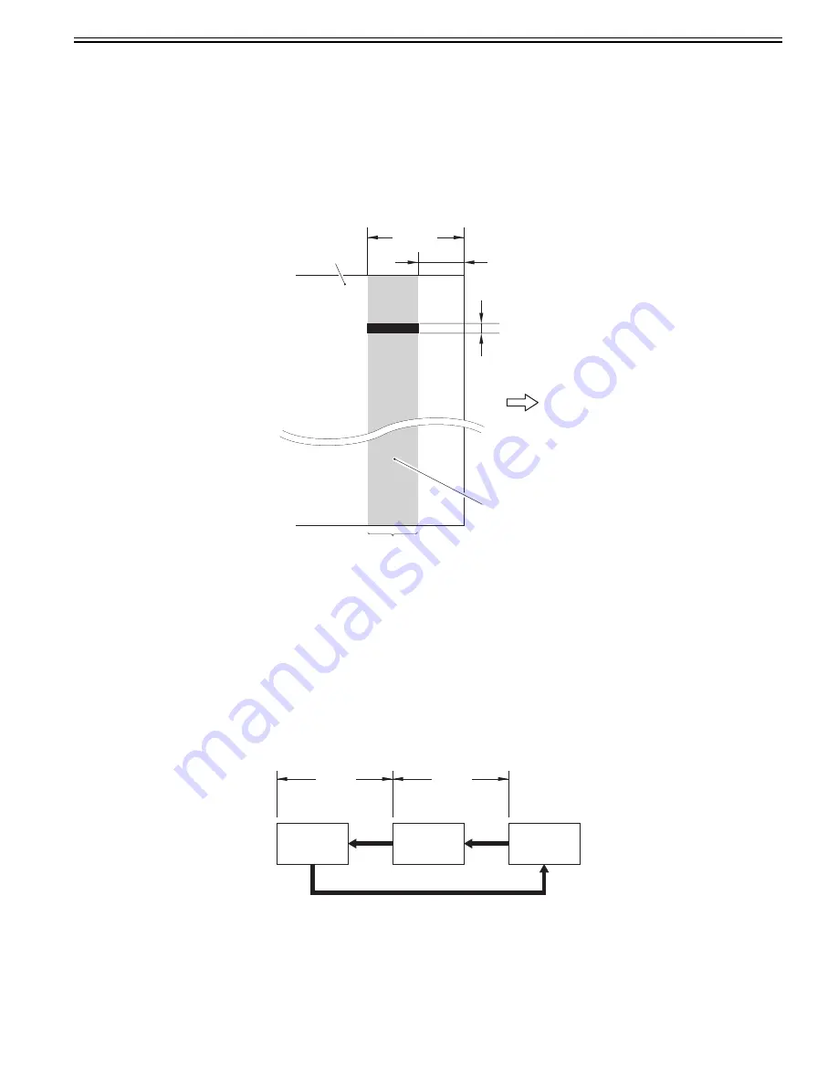
Dust detection
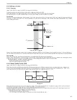
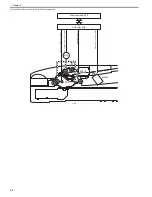
When the CCD scans the leading edge of the document, if there is the object with the width of less than 6 pixels (0.254 mm), length of 24 pixels and the density
from 16/255 to 188/255 in the area of 1.0 to 2.0 mm (equivalent to 24 pixels) from the leading edge of the document, the machine determines that "dust is adhered
to the scanning glass surface".
F-4-8
However, since the dust detection control system is designed to perform detection for A4-size document, it is only applied in the area of 103 mm at both sides (=
206 mm) based on the center line. For a document of which width is larger than A4-size, there is an area at both edges where dust detection control is not performed.
Dust correction
When dust is detected, the correction of removing the dust is automatically performed based on the scanned data.
However, when a document does not have a margin or it has an image on the margin, the machine determines that dust is adhered to the scanning glass surface,
which may cause incorrect correction to be performed. In such a case, disabling of the correction can be set in the user mode.
Adjustment/Cleaning > Automatic correction of feeder dust
ON: Perform automatic correction (initial setting)
OFF: Do not perform automatic correction.
4.3.4.2 Stream Reading Position Shift
0019-9722
imageCLASS MF9170c / imageCLASS MF9150c / imageCLASS MF8450c
When dust is detected at the final document in the job, the stream reading position is shifted to prevent dust lines from being printed in the subsequent job.
There are three stream reading positions, and the position is shifted sequentially every time dust is detected when the job is completed ([A] --> [B] --> [C]).
When dust is detected at the 3rd detection, the stream reading position returns to the original position ([C] --> [A]).
F-4-9
When dust is detected in three jobs consecutively, the alarm message "The scanning assembly is dirty" is displayed in a pop-up window on the control panel.
The alarm message disappears when pressing the [OK] button displayed in the pop-up window.
When the subsequent job is started or the power is turned OFF/ON, information such as the number of times dust was detected or scanning positions is reset.
Disabling of display of the alarm message can be set in the user mode.
Common specification settings > Display of the error for feeder dust
ON: Display the alarm message. (Initial setting)
OFF: Do not display the alarm message (It is possible to set the dust detection function only.)
Area equivalent to 24 pixels
Feed direction
0.254 mm
(Area equivalent
to 6 pixels)
1.0 mm
2.0 mm
Dust detection area
Document
C
0.3 mm
0.3 mm
2nd
detection
3rd detection
B
A
1st
detection
Summary of Contents for imageCLASS MF8450c
Page 16: ...Chapter 1 Introduction ...
Page 55: ...Chapter 2 Basic Operation ...
Page 61: ...Chapter 3 Main Controller ...
Page 75: ...Chapter 4 Original Exposure System ...
Page 88: ...Chapter 5 Original Feeding System ...
Page 105: ...Chapter 6 Laser Exposure ...
Page 113: ...Chapter 7 Image Formation ...
Page 150: ...Chapter 8 Pickup and Feed System ...
Page 184: ...Chapter 9 Fixing System ...
Page 200: ...Chapter 10 External and Controls ...
Page 230: ...Chapter 11 Maintenance and Inspection ...
Page 233: ...Chapter 12 Measurement and Adjustments ...
Page 237: ...Chapter 13 Correcting Faulty Images ...
Page 260: ...Chapter 14 Error Code ...
Page 272: ...Chapter 15 Special Management Mode ...
Page 280: ...Chapter 16 Service Mode ...
Page 322: ...Chapter 17 Upgrading ...
Page 327: ...Chapter 17 17 4 3 Click Next F 17 4 4 Select a USB connected device and click Next F 17 5 ...
Page 328: ...Chapter 17 17 5 5 Click Start F 17 6 6 Click Yes F 17 7 Download will be started F 17 8 ...
Page 330: ...Chapter 18 Service Tools ...
Page 334: ...Appendix ...
Page 349: ......

