Chapter 16
16-38
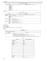
<FACULTY>
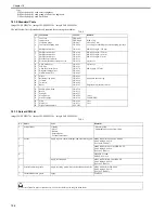
T-16-68
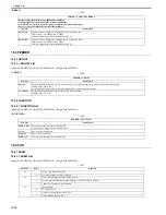
16.5.5 PANEL
16.5.5.1 PANEL List
0020-2028
imageCLASS MF9170c / imageCLASS MF9150c / imageCLASS MF8450c
<PANEL>
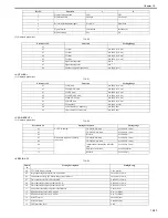
T-16-69
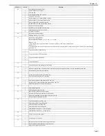
T-16-70
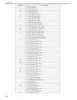
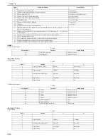
V34G3TX
SPEED
Close DC circuit to deliver the selected frequency using the modem's G3 signal delivery function (V. 34)
3429baud
3200baud
3000baud
2800baud
2743baud
2400baud
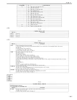
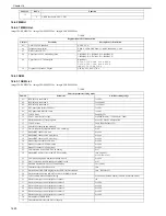
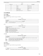
TESTMODE > FAX > FACULTY
Sub item
Description
G34800TX
G34 800TX
Close DC circuit to deliver the frequency of 4800bps using the modem's G3 signal delivery function.
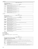
DETECT1
CI
Ring detection
Check Ci, Fc and hook state (ON, OFF) from l-line.
CI FREQ
HOOK
FC
DETECT2
CMG
CNG detection test 1
Check CNG signal and FED
Make CML relay at ON state to detect CNG
FED
CML
DETECT3
CMG
CNG detection test 2
Check CNG signal and FED
Make CML relay at OFF state to detect CNG
FED
CML
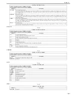
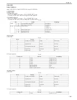
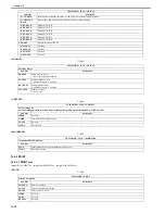
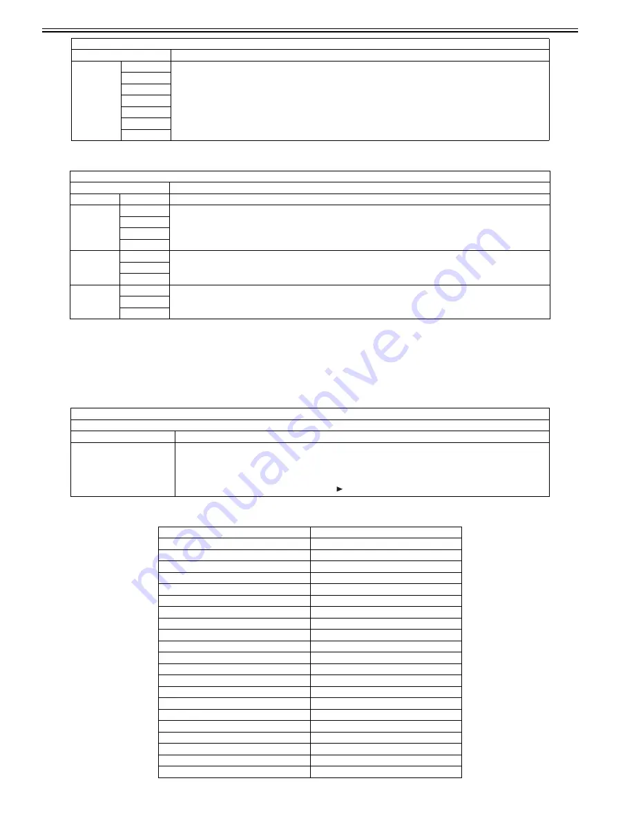
TESTMODE > PANEL
Key, wheel, LCD, LED, and flicker check
Sub item
Description
KEY CHECK START
Key check
Check the operation of the key on the control panel.
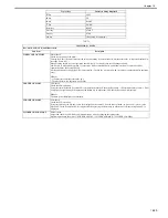
The following table shows information displayed when pressing each key.
When pressing the OK key after operation check, OK or NG is displayed in the following condition.
OK: Operation was correctly performed for all keys.
NG: A failure occurred to key operation. (Clicking the key displays the keys which have not been pressed sequentially.)
Type of Key
Character String Displayed
Main Menu key
MAIN
Custom key 1
COPY
Custom key 2
SEND
Status monitor/Cancel key
JOB
Left any key
MENU-L
Right any key
MENU-R
1
1
2
2
3
3
4
4
5
5
6
6
7
7
8
8
9
9
*
*
0
0
#
#
Log in/out key
ID
Clear key
C
Back key
RETURN
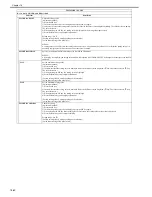
TESTMODE > FAX > MODEM
Sub item
Description
Summary of Contents for imageCLASS MF8450c
Page 16: ...Chapter 1 Introduction ...
Page 55: ...Chapter 2 Basic Operation ...
Page 61: ...Chapter 3 Main Controller ...
Page 75: ...Chapter 4 Original Exposure System ...
Page 88: ...Chapter 5 Original Feeding System ...
Page 105: ...Chapter 6 Laser Exposure ...
Page 113: ...Chapter 7 Image Formation ...
Page 150: ...Chapter 8 Pickup and Feed System ...
Page 184: ...Chapter 9 Fixing System ...
Page 200: ...Chapter 10 External and Controls ...
Page 230: ...Chapter 11 Maintenance and Inspection ...
Page 233: ...Chapter 12 Measurement and Adjustments ...
Page 237: ...Chapter 13 Correcting Faulty Images ...
Page 260: ...Chapter 14 Error Code ...
Page 272: ...Chapter 15 Special Management Mode ...
Page 280: ...Chapter 16 Service Mode ...
Page 322: ...Chapter 17 Upgrading ...
Page 327: ...Chapter 17 17 4 3 Click Next F 17 4 4 Select a USB connected device and click Next F 17 5 ...
Page 328: ...Chapter 17 17 5 5 Click Start F 17 6 6 Click Yes F 17 7 Download will be started F 17 8 ...
Page 330: ...Chapter 18 Service Tools ...
Page 334: ...Appendix ...
Page 349: ......

