Chapter 7
7-6
7.1.6 Fixing Block
0019-5017
imageCLASS MF9170c / imageCLASS MF9150c / imageCLASS MF8450c
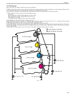
In this block, a toner image is fixed on paper.
The toner image transferred to the paper can be smeared easily by hands since it is only attracted to the paper by a static electricity.
When pressure and heat are applied to the paper and toner image, the toner image melts with mixed colors and becomes a permanent printed image (on-demand
fixing).
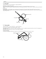
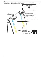
Step 9: Fixing
When the paper with toner is transported between the fixing sleeve and the pressure roller, the toner is melted by heat and fixed to the paper by pressure.
For the fixing heater, the machine uses a ceramic heater with lower heat, which warms up quickly. The feature of this heater is that the wait time is short and thus
energy saving is realized.
F-7-11
7.1.7 Cleaning Block
0019-5018
imageCLASS MF9170c / imageCLASS MF9150c / imageCLASS MF8450c
In this block, the residual toner on the photosensitive drum is removed.
When transfer is performed, a part of the toner image on the photosensitive drum is not sometimes transferred and remains on the drum. This remaining toner is
called residual toner.
Removing the residual toner keeps a clear image in the subsequent print operation.
Step 10: Drum cleaning
The residual toner on the photosensitive drum is scraped by the cleaner blade, and then collected into the waste toner container.
F-7-12
Fixing sleeve
Fixing heater
Pressure roller
Toner
Paper
Waste toner container
Cleaner blade
Photosensitive
drum
residual toner
Summary of Contents for imageCLASS MF8450c
Page 16: ...Chapter 1 Introduction ...
Page 55: ...Chapter 2 Basic Operation ...
Page 61: ...Chapter 3 Main Controller ...
Page 75: ...Chapter 4 Original Exposure System ...
Page 88: ...Chapter 5 Original Feeding System ...
Page 105: ...Chapter 6 Laser Exposure ...
Page 113: ...Chapter 7 Image Formation ...
Page 150: ...Chapter 8 Pickup and Feed System ...
Page 184: ...Chapter 9 Fixing System ...
Page 200: ...Chapter 10 External and Controls ...
Page 230: ...Chapter 11 Maintenance and Inspection ...
Page 233: ...Chapter 12 Measurement and Adjustments ...
Page 237: ...Chapter 13 Correcting Faulty Images ...
Page 260: ...Chapter 14 Error Code ...
Page 272: ...Chapter 15 Special Management Mode ...
Page 280: ...Chapter 16 Service Mode ...
Page 322: ...Chapter 17 Upgrading ...
Page 327: ...Chapter 17 17 4 3 Click Next F 17 4 4 Select a USB connected device and click Next F 17 5 ...
Page 328: ...Chapter 17 17 5 5 Click Start F 17 6 6 Click Yes F 17 7 Download will be started F 17 8 ...
Page 330: ...Chapter 18 Service Tools ...
Page 334: ...Appendix ...
Page 349: ......

