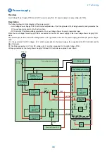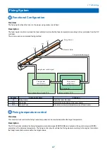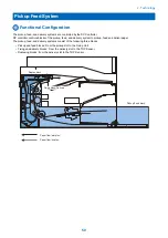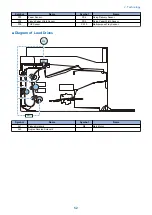
DC Controller
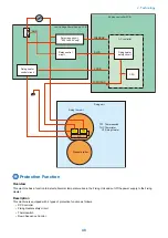
The DC Controller monitors temperature of the Thermistor at all time. When abnormal temperature is detected, the DC
Controller stops the output of Fixing Heater control signal, and turns OFF relays (RL101) to shut off the power supply to the
Fixing Heater.
Fixing Heater safety circuit
Fixing Heater safety circuit monitors temperature of the Thermistor at all time. When abnormal temperature is detected, the
Fixing Heater turns OFF relays (RL101) to shut off the power supply to the Fixing Heater.
Thermoswitch
When the temperature of the Fixing Heater rises abnormally high, the Thermoswitch opens to shut off the power supply to the
Fixing Heater.
Down Sequence Control
When the temperature of the Fixing Heater exceeded the threshold value, the machine delivers paper being printed, drives the
fan and repeats the stopped state (approx. 30 seconds) and 50% reduced productivity state to decrease the temperature.
*1: Number of sheets corresponding to 50% productivity with LTR (approx. 18 sheets, 1-suded) are fed.
Fixing Unit Failure Detection
Overview
The DC Controller shuts down the power supply to the Fixing Unit and notifies an error when the Fixing Unit is in the following
condition.
• Startup failure
• Abnormal high temperature failure
• Abnormal low temperature failure
• Fixing drive circuit error
Description
Fixing Unit startup failure
An error code is notified if the Fixing Unit does not reach a certain temperature within a specified period of time.
Abnormal high temperature failure
An error code is notified if an abnormally high temperature is detected in the Fixing Unit.
Abnormal low temperature failure
An error code is notified if an abnormally low temperature is detected in the Fixing Unit.
Fixing Unit drive circuit error
An error code is notified if an abnormality is detected in the Fixing Unit drive circuit.
Error Code
E000: Startup failure
• E000-0000: Fixing Unit startup failure
E001: Abnormal high temperature failure
• E001-0000: Abnormal high temperature of Fixing Unit
E003: Abnormal low temperature failure
• E003-0000: Abnormal low temperature of Fixing Unit
E004: Fixing drive circuit error
• E004-0000: Fixing Heater drive circuit error
2. Technology
49
Summary of Contents for imageCLASS MF264dw
Page 13: ...Product Overview 1 Product Lineup 6 Features 8 Specifications 9 Parts Name 14 ...
Page 67: ...Consumable Parts Consumable parts are not required in this machine 3 Periodical Service 59 ...
Page 68: ...Periodical Service No periodic services are required to this machine 3 Periodical Service 60 ...
Page 89: ...3 80 mm 80 mm 4 Parts Replacement and Cleaning 81 ...
Page 92: ... If the Fax is not installed 3x 2x 1x 2 60 mm 3 4 Parts Replacement and Cleaning 84 ...
Page 96: ...3 4 Parts Replacement and Cleaning 88 ...
Page 97: ...4 5 4 Parts Replacement and Cleaning 89 ...
Page 105: ...2 3 1x 4 Parts Replacement and Cleaning 97 ...
Page 110: ...5 6 4x 1x 1x 7 4 Parts Replacement and Cleaning 102 ...
Page 115: ...3 4 5 4 Parts Replacement and Cleaning 107 ...
Page 116: ...6 4 Parts Replacement and Cleaning 108 ...
Page 122: ...2 3 4 4 Parts Replacement and Cleaning 114 ...
Page 124: ...1 2 2x 3 4 4 Parts Replacement and Cleaning 116 ...
Page 127: ...2 3 4 2x 1x 5 4 Parts Replacement and Cleaning 119 ...
Page 129: ...3 4 2x 1x 5 6 4 Parts Replacement and Cleaning 121 ...
Page 132: ...5 2x 4 Parts Replacement and Cleaning 124 ...
Page 138: ...2 1x 3 1x 4 4 Parts Replacement and Cleaning 130 ...
Page 140: ... Procedure 1 2 4 Parts Replacement and Cleaning 132 ...
Page 144: ... Procedure 1 2 3 2x 4 Parts Replacement and Cleaning 136 ...
Page 146: ...3 4 4 Parts Replacement and Cleaning 138 ...
Page 147: ...5 4 Parts Replacement and Cleaning 139 ...
Page 153: ...1 2 3 4 4 Parts Replacement and Cleaning 145 ...
Page 155: ...1 2 2x 3 4 4 Parts Replacement and Cleaning 147 ...
Page 158: ...2 3 4 2x 1x 5 4 Parts Replacement and Cleaning 150 ...
Page 160: ...3 4 2x 1x 5 6 4 Parts Replacement and Cleaning 152 ...
Page 163: ...5 2x 4 Parts Replacement and Cleaning 155 ...
Page 166: ...2 2x 1x 1x 3 1x 1x 4 Parts Replacement and Cleaning 158 ...
Page 170: ...2 2x 3 4 2x 4 Parts Replacement and Cleaning 162 ...
Page 173: ...2 3 4 2x 1x 5 4 Parts Replacement and Cleaning 165 ...
Page 175: ...3 4 2x 1x 5 6 4 Parts Replacement and Cleaning 167 ...
Page 178: ...5 2x 4 Parts Replacement and Cleaning 170 ...
Page 183: ...2 4x 4 Parts Replacement and Cleaning 175 ...
Page 188: ... If the Fax is not installed 6 2x 1x 7 3x 8 2x 1x 4 Parts Replacement and Cleaning 180 ...
Page 191: ...4 1x 5 1x 6 3x 4 Parts Replacement and Cleaning 183 ...
Page 199: ... Procedure 1 3x 2x 4 Parts Replacement and Cleaning 191 ...
Page 201: ... If the Fax is not installed 2 4x 3 4 Parts Replacement and Cleaning 193 ...
Page 208: ...4 4 Parts Replacement and Cleaning 200 ...
Page 211: ...3 2x 4 1x 4 Parts Replacement and Cleaning 203 ...
Page 213: ...2 3 4x 4 4 Parts Replacement and Cleaning 205 ...
Page 217: ...3 1x 1x 4 5 2x 6 4 Parts Replacement and Cleaning 209 ...
Page 218: ...7 8 9 4 Parts Replacement and Cleaning 210 ...
Page 223: ...4 4 Parts Replacement and Cleaning 215 ...
Page 228: ...Adjustment 5 Adjustment at Parts Replacement 221 ...
Page 230: ...Troubleshooting 6 Test Print 223 Troubleshooting Items 226 Debug Log 228 Version Upgrade 231 ...
Page 242: ...Error Jam Alarm 7 Overview 235 Error Code 238 Jam Code 241 Alarm Code 243 ...
Page 251: ...Alarm Code This machine does not have any Alarm Code 7 Error Jam Alarm 243 ...
Page 287: ...APPENDICES Service Tools 280 General Circuit Diagram 281 Backup Data 283 ...


