Chapter 3
3-15
F-3-65
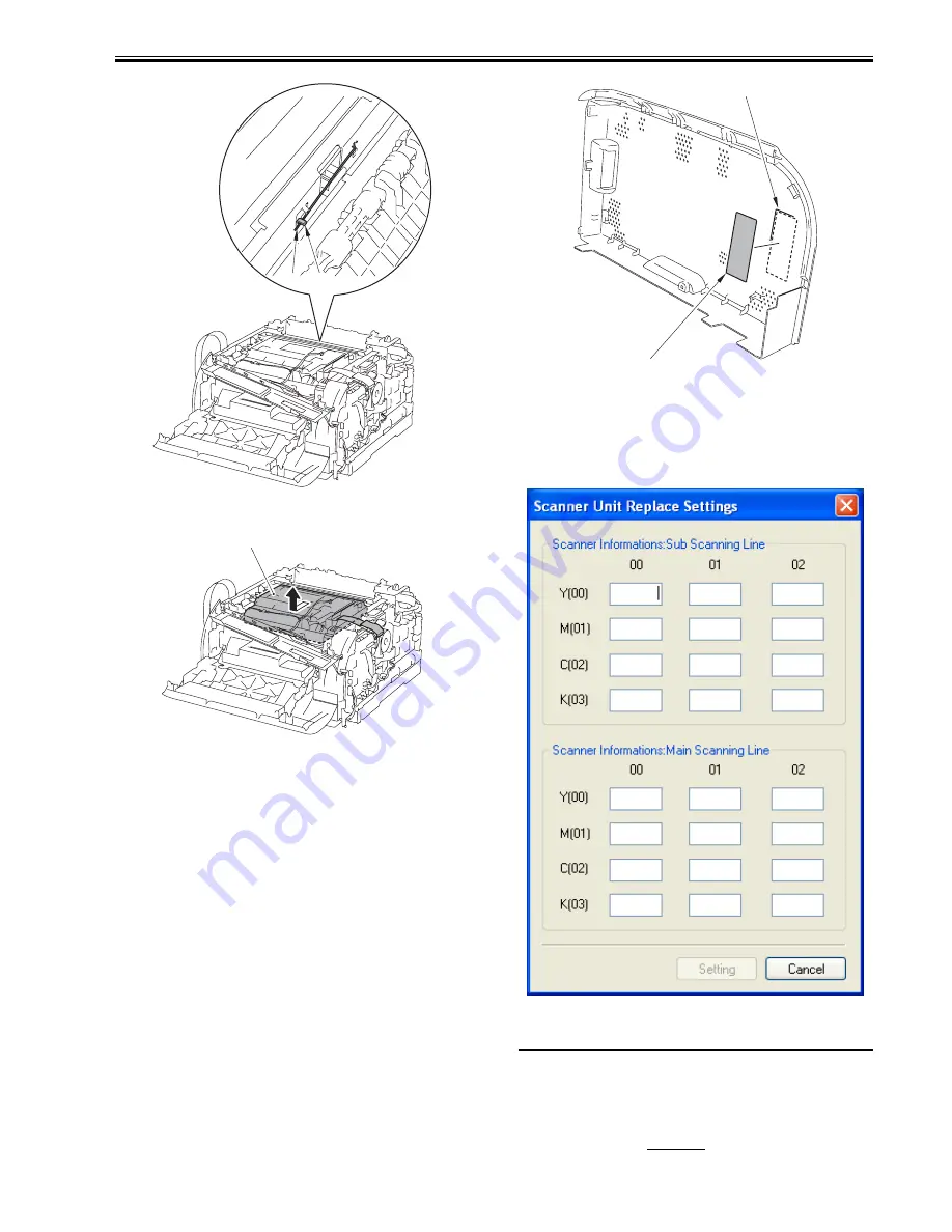
11) Remove the laser scanner unit [1].
F-3-66
3.2.1.3 After Replacing the laser scanner unit
0019-6099
LBP5050N / LBP5050
When replacing the laser unit, enter the value described on the label included
in the scanner unit into the following service mode.
After entry, put the label [2] inside the right cover [1].
F-3-67
How to transit to the service mode
1. After the power ON, display the printer driver screen.
2. Change the display from the driver screen to status window.
3. Enter the password “*28*” with keyboards.
4. Select: Option menu > Service mode > Service parts replacement > Scan-
ner unit replace settings from the status window.
F-3-68
3.3 IMAGE FORMATION SYSTEM
3.3.1 Intermediate Transfer Unit
3.3.1.1 Before Removing the ITB Unit
0018-7539
LBP5050N / LBP5050
1) Remove the right cover.
(page 3-2)
[Removing the Right Cover]
[2]
[1]
[1]
[2]
[1]
Summary of Contents for I-Sensys LBP5050
Page 1: ...Aug 13 2008 Service Manual LBP5050 Series ...
Page 2: ......
Page 6: ......
Page 11: ...Chapter 1 PRODUCT DESCRIPTION ...
Page 12: ......
Page 14: ......
Page 22: ......
Page 23: ...Chapter 2 TECHNICAL REFERENCE ...
Page 24: ......
Page 45: ...Chapter 3 DISASSEMBLY AND ASSEMBLY ...
Page 46: ......
Page 70: ...Chapter 3 3 22 F 3 92 2 Remove the fixing motor 1 1 connector 2 2 screws 3 F 3 93 1 2 1 2 3 3 ...
Page 71: ...Chapter 4 MAINTENANCE AND INSPECTION ...
Page 72: ......
Page 74: ......
Page 77: ...Chapter 5 TROUBLESHOOTING ...
Page 78: ......
Page 80: ......
Page 90: ...Chapter 5 5 10 F 5 11 F 5 12 ...
Page 91: ...Chapter 5 5 11 F 5 13 F 5 14 ...
Page 93: ...Chapter 5 5 13 00 Cyan 01 Magenta 02 Yellow 03 black F 5 17 ...
Page 94: ......
Page 95: ...Chapter 6 APPENDIX ...
Page 96: ......
Page 98: ......
Page 102: ......
Page 103: ...Aug 13 2008 ...
Page 104: ......


