COPYRIGHT © 1998 CANON INC. FINISHER-C1/SADDLE FINISHER-C2 REV. 0 DEC. 1998 PRINTED IN JAPAN (IMPRIME AU JAPON)
2-5
CHAPTER 2 FINISHER UNIT BASIC OPERATION
3.
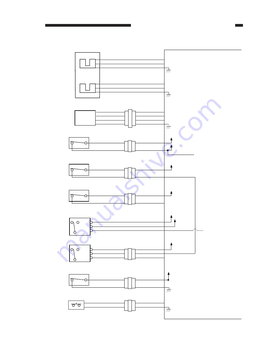
Inputs to the Finisher Controller PCB
+5V
J15-10
-12
-11
J400-6
-4
-5
PI9
+5V
J12-10
-12
-11
J400-3
-1
-2
PI19
+5V
V0
Vin
J6-2
-1
-3
-4
-3
-4
-2
-1
J114-2
-1
-3
-4
-3
-4
-2
-1
PS1
J212
N.O.
+24V
DROPN
TRYSAFE
MS1
J112
J5-1
-3
N.O.
MS6
J209
J5-11
-12
-1
-2
N.C.
-3
-4
-2
-1
N.O.
+24VSHIFT
+24VSHIFT
+24VMOVE
+24VMOVE
+24VMOVE
+24VSHIFT
MS2
J209
J5-10
-9
-1
-2
MS5
J132
J5-8
-7
-2
-1
-3
-2
-1
J206
J5-4
-5
-6
J131-1
-2
-3
C.
N.O.
N.C.
MS3
J7-1
-2
-3
N.C.
N.O.
C.
MS4
TP1
J12-14
-13
THMSW
J135
SWGGOPN
SHUTCL
+24VMOVE
Tray lift
motor clock
sensor 2
Tray lift
motor clock
sensor 1
Height
sensor
Sensor PCB
Door switch
Swing guide closed detecting switch 1
Swing guide closed detecting switch 2
Safety zone switch
Shutter closed detecting switch
Tray upper limit detecting switch
Tray lift motor thermal switch
Finisher controller PCB
While the tray lift motor is
rotating, alternately between '1'
and '0'.
While the tray lift motor is
rotating, alternately between '1'
and '0'.
Measures the distance between
sensor and top of the stack on
the tray.
When the front door
and the upper cover
are closed, '0'.
When the tray is at the
delivery slot, '1'.
When the shutter
is closed, '1'.
When the switch temperature
exceeds about 73.5
O
C, '1'; when
it drops thereafter to about 40
O
C
or less, '0'.
SFTCLK2
SFTCLK1
TRYLMT
When the tray is
at the upper limit, '1'.
Figure 2-105


