Part 3: Adjustment
3-11
2. CIRCUIT ADJUSTMENTS
[Adjustment conditions]
●
Input signal
Video signal ............................1.0Vp-p/75
Ω
terminated, 16 steps gray scale
(Composite video signal)
Computer signal .....................0.7Vp-p/75
Ω
terminated, 16 steps gray scale pattern
Component Video signal .........0.7Vp-p/75
Ω
terminated, 16 steps gray scale
(Component video signal with 480p, 575p, 720p or
1080i format)
●
Picture control mode
...............“STANDARD” mode unless otherwise noted.
Note:
Please refer to “Service Adjustment Menu Operation” for entering the service mode and
adjusting the service data.
2.1 Output Voltage Adjustment
After replacing the Power Board readjust the Output voltage adjustment as follows.
1. Connect a digital voltmeter to pins 1 (+) and 3 (–) of
K6D
.
2. Adjust the voltage by using
VR611
as following.
AC Input: 230V Reading: 380V ± 2V
* This adjustment is not required even if the power board is replaced because this
adjustment is carried out before parts shipment.
Fig. 3-2
The each circuit has been made by the fine adjustment at factory. Do not
attempt to adjust the following adjustments except requiring the
readjustments in servicing otherwise it may cause loss of performance
and product safety.
CAUTION
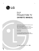
White 100%
Black 100%
16 steps gray scale pattern
Be sure to connect the lamp when taking this adjustment.
CAUTION
Summary of Contents for D78-5452
Page 9: ...Part 1 General Information ...
Page 25: ...Part 2 Repair Information ...
Page 43: ...Part 3 Adjustment ...
Page 66: ...Part 4 Troubleshooting ...
Page 78: ...Part 4 Troubleshooting 4 12 AN5870 RGB SYNC SW IC1201 IC5201 BA7078 Sync Separator IC5341 ...
Page 80: ...Part 4 Troubleshooting 4 14 CXD3536 LCD Driver IC401 FA5502 P F Control IC621 ...
Page 81: ...Part 4 Troubleshooting 4 15 M62392 M62393 D A IC6271 IC281 ML60851 USB Driver IC9801 ...
Page 83: ...Part 4 Troubleshooting 4 17 TC90A69F Y C Separator IC2101 ...
Page 84: ...Part 5 Parts Catalog ...
Page 85: ......
Page 99: ...Part 6 Electrical Diagrams ...