


Chapter 15
15-2
- Check the wiring for trapping and loose screws.
- Check the external cover are all fitted properly.
- Check the main power switch/control panel power switch are at the ON side.
- Check the power cable/signal cable to accessories are correctly routed.
- Check the cover switch operates normally.
- Check the fuses on the PCBs to see if they have blown.
- Check the user knows how to use the machine correctly.
15.1.5 Others
0014-3018
Color iR C3380G / Color iR C2880G / Color iR C3380i / Color iR C3380 / Color iR C2880i / Color iR C2880 / iR C3480 / iR C3480i / iR C3080i / iR C2550
If a machine is brought in from a cold to a warm place, its inside can develop condensation, which will lead to various problems.
(1) condensation on the BD sensor can cause faults associated with E100.
(2) condensation on the dust-blocking glass can cause the images in sub scanning direction to be too light.
(3) condensation on the contact sensor of the reader unit or the copyboard glass can lead to light images.
(4) condensation on the pickup/feed guide can cause faulty paper movement.
If (4) above is noted, be sure to dry wipe the units involved in the feed system.
The same is true of toner cartridges and drum units, i.e., when they are unpacked after being brought in from a cold place. To prevent condensation, advise the user
to leave the package alone (for about 1 to 2 hr) before opening it.
15.2 Test Print
15.2.1 Overview
0013-8865
Color iR C3380G / Color iR C2880G / Color iR C3380i / Color iR C3380 / Color iR C2880i / Color iR C2880 / iR C3480 / iR C3480i / iR C3080i / iR C2550
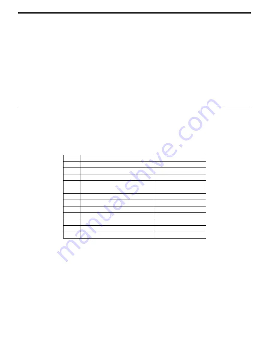
The machine offers the following 6 types of test prints (TYPE), each designed for identification of a specific type of image fault. The data for these test prints is
prepared by the main controller: if the output of a test print is free of the fault in question, suspect a fault on the BDL/PCL/PS input or the reader unit.
15.2.2 TYPE of test print
0013-8868
Color iR C3380G / Color iR C2880G / Color iR C3380i / Color iR C3380 / Color iR C2880i / Color iR C2880 / iR C3480 / iR C3480i / iR C3080i / iR C2550
T-15-1
15.2.3 Selecting Test Print TYPE
0013-8871
Color iR C3380G / Color iR C2880G / Color iR C3380i / Color iR C3380 / Color iR C2880i / Color iR C2880 / iR C3480 / iR C3480i / iR C3080i / iR C2550
1) Set the copy count, paper size, and pickup mode (single-sided or double-sided).
2) Make the following selections in service mode: COPIER>TEST>PG.
3) Make the following selections: COPIER>TEST>PG>TYPE.
4) Enter the appropriate TYPE No. using the keypad, and press the OK key.
5) Select the appropriate color using COLOR-Y/M/C/K (output at 1).
6) Set the density using DENS-Y/M/C/K (valid only if TYPE=5).
7) Set the image mode by TXPH
8) Press the start key.
Type No.
Description
Originator
0
normal copy/print
-
1-3
- (for R&D)
-
4
16 gradations
Main controller PCB (main)
5
full half-tone
Main controller PCB (main)
6
grid
Main controller PCB (main)
7-9
- (for R&D)
-
10
MCYBk horizontal stripe (sub scanning direction)
Main controller PCB (main)
11
- (for R&D)
-
12
64 gradations
Main controller PCB (main)
13
- (for R&D)
-
14
full color 16 gradations
Main controller PCB (main)
15-100
- (for R&D)
-
Summary of Contents for Color iR C3480
Page 2: ......
Page 27: ...Chapter 1 Introduction ...
Page 28: ......
Page 47: ...Chapter 1 1 18 F 1 14 ON OFF ON OFF ...
Page 70: ...Chapter 1 1 41 5 Turn on the main power switch ...
Page 79: ...Chapter 2 Installation ...
Page 80: ......
Page 85: ...Chapter 2 2 3 Not available in some regions ...
Page 134: ...Chapter 3 Basic Operation ...
Page 135: ......
Page 137: ......
Page 143: ...Chapter 4 Main Controller ...
Page 144: ......
Page 152: ...Chapter 4 4 6 F 4 6 CPU HDD ROM access to the program at time of execution ...
Page 171: ...Chapter 5 Original Exposure System ...
Page 172: ......
Page 203: ...Chapter 6 Laser Exposure ...
Page 204: ......
Page 206: ......
Page 220: ...Chapter 7 Image Formation ...
Page 221: ......
Page 277: ...Chapter 8 Pickup Feeding System ...
Page 278: ......
Page 282: ......
Page 336: ...Chapter 9 Fixing System ...
Page 337: ......
Page 339: ......
Page 357: ...Chapter 10 Externals and Controls ...
Page 358: ......
Page 362: ......
Page 366: ...Chapter 10 10 4 F 10 2 F 10 3 FM1 FM2 FM5 FM8 FM11 FM4 FM3 FM6 FM7 FM9 FM10 ...
Page 375: ...Chapter 10 10 13 F 10 10 2 Remove the check mark from SNMP Status Enabled ...
Page 376: ...Chapter 10 10 14 F 10 11 ...
Page 402: ...Chapter 11 MEAP ...
Page 403: ......
Page 405: ......
Page 452: ...Chapter 12 RDS ...
Page 453: ......
Page 455: ......
Page 464: ...Chapter 13 Maintenance and Inspection ...
Page 465: ......
Page 467: ......
Page 469: ...Chapter 13 13 2 F 13 1 8 9 1 2 3 3 5 6 7 10 11 12 13 14 4 ...
Page 474: ...Chapter 14 Standards and Adjustments ...
Page 475: ......
Page 477: ......
Page 485: ......
Page 486: ...Chapter 15 Correcting Faulty Images ...
Page 487: ......
Page 495: ...Chapter 15 15 4 F 15 2 COLOR M 1 COLOR Y C K 0 ...
Page 569: ...Chapter 15 15 78 F 15 82 J102 J107 J103 J108 J101 J109 J106 J112 J115 J113 J114 J104 J105 ...
Page 570: ...Chapter 16 Self Diagnosis ...
Page 571: ......
Page 573: ......
Page 600: ...Chapter 17 Service Mode ...
Page 601: ......
Page 603: ......
Page 712: ...Chapter 18 Upgrading ...
Page 713: ......
Page 715: ......
Page 746: ...Chapter 19 Service Tools ...
Page 747: ......
Page 749: ......
Page 752: ...APPENDIX ...
Page 774: ......


