CHAPTER 3
3 - 11
COPYRIGHT ©
2000 CANON INC. CANOSCAN D660U REV.0 JULY 2000 PRINTED IN JAPAN (IMPRIME AU JAPON)
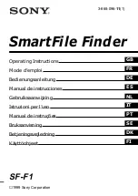
q
Button Cable
w
Screw
e
Main PCB
r
Flat Cable
t
Ferrite Core Holder
Figure 3-14
2. Precaution when attaching the main PCB
1) Remove two screws to remove the ferrite core holder temporarily.
2) Connect the flat cable to the main PCB.
3) Bend the button cable at 90 degrees when connecting to the main PCB as shown in Figure
3-14.
IV. PCB
A. Main PCB
1. Removing the main PCB
1) Remove the document cover.
2) Remove the document glass unit.
3) Remove the flat cable, button cable, and two screws, then remove the main PCB.
1
4
3
2
2
3
4
5
1
5
1
90