Chapter 1
6
UFRII LT PRINTER KIT-J2 is mounted)
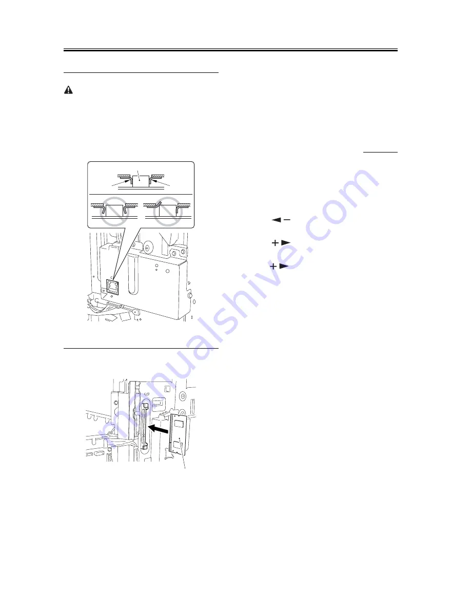
When attaching the LAN cover, take care not to dam-
age the grounding plate [2] by the LAN port [1].
Also, after attaching the LAN cover, check to make
sure that the grounding plate is in firm contact with the
LAN port.
F-1-15
16) Mount the 256MB RAM [1].
F-1-16
17) Put back the parts that have been removed.
- RAM cover
- the connector of the IP-modem cable (if a Super
G3 Fax Board-T1 is mounted)
- rear left cover
- rear cover
18) Connect the power plug, and turn on the main
power switch.
1.2.2 Checking the Con-
nection
0010-7789
When you have installed the kit, go through the fol-
lowing to make sure that it is properly recognized:
1) Start service mode.
User Mode key > 2 > 8 > Use Mode key
In response, [#SSSW] appears.
2) Press [
] 5 times. When [REPORT] has ap-
peared, press [OK].
3) Press [
] once. When [REPORT OUTPUT]
has appeared, press [OK].
4) Press [
] 5 times. When [SPEC LIST] has ap-
peared, press [OK].
5) See that a SPEC REPORT is printed out. Check to
be sure that 'PCL' is 'ON'.
[1]
[2]
[2]
[1]
Summary of Contents for BW PCL PRINTER KIT-J1
Page 1: ...Sep 14 2005 Installation Procedure Canon BW PCL PRINTER KIT J1 ...
Page 2: ......
Page 6: ......
Page 8: ...Contents ...
Page 9: ...Chapter 1 Installation Procedure ...
Page 15: ...Sep 14 2005 ...
Page 16: ......


