background image


CANNON Instrument Company | TE-BBR System Preparation & Maintenance 

19 


TE-BBR System Preparation & Maintenance 


Note:


Complete the TE-BBR assembly before beginning procedures in this 

section. 

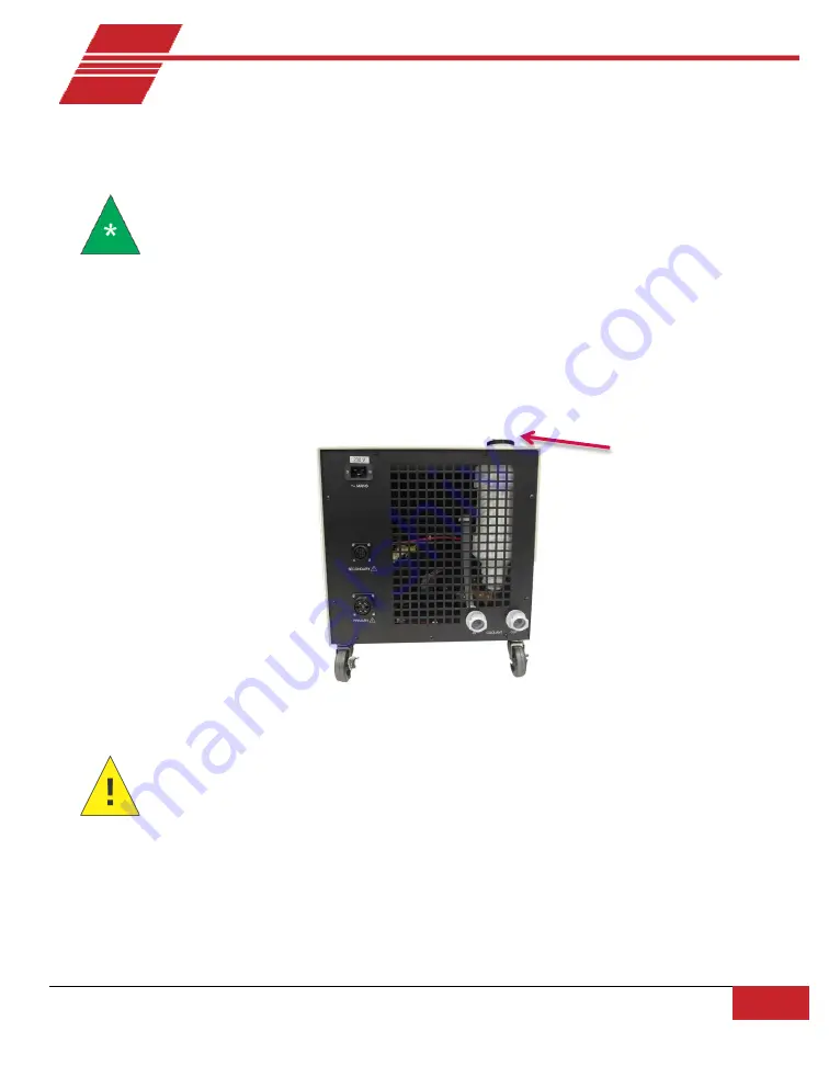
Fill the Air/Water Heat Exchanger 

Obtain a supply of quality ethylene glycol (automotive antifreeze) and mix it with water in a ratio of 
30 percent ethylene glycol to 70 percent water. After the Exchanger tubing connections are secured 
(see section Tubing Connections), pour the mixture into the reservoir opening on the top of the 
Air/Water Heat Exchanger until it is full (approximately 1-2 liters). Refer to Figure 13. 


Figure 13: Air/Water Heat Exchanger Reservoir 


Caution:


Replace water/anitfreeze mixture annually to ensure reliable 

performance and prevention of corrosion of internal components. Ethylene


glycol is a toxic substance. Use proper safety measures when handling. Follow 
appropriate (M)SDS procedures.


Do not use "environmentally friendly” alternatives to ethylene glycol (such as polyethylene glycol) in 
the heat exchanger. Such products can coagulate under colder conditions and damage the TE-BBR 
circulation system. 

Reservoir 

Summary of Contents for TE-BBR

Page 1: ...Instruction Operation Manual 44 0991 Thermo Electric Bending Beam Rheometer TE BBR ...

Page 2: ......

Page 3: ...o are registered trademarks of Cannon Instrument Company Contact Address CANNON Instrument Company 2139 High Tech Road State College PA 16803 USA Phone 1 814 353 8000 1 800 676 6232 Fax 1 814 353 8007 Website www cannoninstrument com Email Sales sales cannoninstrument com Service service cannoninstrument com ...

Page 4: ...4 Safety Precautions 5 Notes Cautions Warnings 5 Safety Precautions 5 Specifications 7 Ordering Information 9 Unpack and Install the TE BBR 11 System Components Arrangement 12 Control Unit 12 Stirring Bar Protection Sheet 12 Stirring Bar 12 Load Frame 13 Level the Instrument 13 Computer 13 Exchanger Refrigeration 14 Electrical Connections 15 Load Control Unit Connections 15 Control Unit Heat Excha...

Page 5: ...k the Control Unit 22 Control Unit Operation Checklist 22 Initial Software Settings 23 Enable Temperature Control 25 Disable Temperature Control 25 Calibration 26 Thermistor Probe Calibration Procedure 26 LVDT and Load Cell Calibration 26 Compliance 27 Run the Confidence Test 27 Verify Calibration 28 Erratic Readings Error Message 29 Calibrate with the Auto Thickness Option 29 Software Menu Option...

Page 6: ...edure 46 Drain Fluid Procedure 47 Failed Communications 48 Restore the COM Setting 50 Temperature Reading Error 51 Temperature Probe 51 Internal Wiring 52 Confidence Test Failures 52 Level the BBR 52 Incorrect Load Values 53 Fluctuation in Deflection Load During a Test 54 Check the TE BBR Voltage Values for Force and Deflection 54 Download Button 54 Clean the Instrument Housing 55 Adjusting Bendin...

Page 7: ...ion 69 Hazardous materials 69 Shipping notification 69 Appendix 1 Test Reports 70 ASCII File Format for TE BBR Report Files csv 70 ASCII File Format for TE BBR Data Files dat 71 TE BBR Sample Data 73 Appendix 2 Technical Note 0306131 75 BBR Motor Stirrer Installation 75 Install Procedure 75 Appendix 3 Technical Note 0611091 77 BBR Crack Seal Option Installation 77 Replacement Procedure 77 List of ...

Page 8: ...ure 14 Remove Exchanger Tubing Connection 47 Figure 15 Exchanger with Housing Removed 48 Figure 23 Keyway Diagram 51 Figure 24 Bubble Level 53 Figure 25 Diagram A new Figure 26 Diagram B old 59 Figure 27 TE BBR Capacitor 60 Figure 28 Terminal Connections 60 Figure 29 Load Cylinder Air Line Connections 63 Figure 30 Report View 73 Figure 31 Graph View 74 Figure 32 TE BBR Motor Stirrer Plate and AC P...

Page 9: ... and Consumables 9 Table 4 Test Menu Options 30 Table 5 View Menu Options 30 Table 6 Calibrate Menu Options 31 Table 7 TE BBR Replacement Parts 66 Table 8 ASCII File Format 71 Table 9 BBR Crack Seal Kit Components p n 44 0675 77 ...

Page 10: ......

Page 11: ......

Page 12: ...ould have some experience in the handling and testing of asphalt binders and should be familiar with the operation of the Windows operating system Procedural Overview A small beam of asphalt is prepared and placed horizontally on two supports which are submerged in a cold alcohol solution A load is applied at the center of the beam and the deflection of the beam is recorded over a time span of fou...

Page 13: ... Refer to Figure 2 Figure 2 Front of Control Unit Load Frame The Load Frame rests on top of the Control Unit The lower section is immersed in the alcohol bath The Load Frame consists of a frame with the LVDT at the uppermost section a shaft with an attached platform for holding weights an air bearing through which the shaft passes a load cell integral with the shaft below the bearing and at the lo...

Page 14: ...t the load to be applied to the beam Automatic Operation Automatic operation is controlled via the computer The computer sends signals to the electronics system to trigger a solenoid valve which regulates the flow of pressurized air or gas This adjusts the net load applied to the asphalt beam Refer to Figure 4 Air Water Heat Exchanger The Air Water Heat Exchanger consists of a radiator fan s and a...

Page 15: ...section for air pressure and volume requirements which vary depending on the date of manufacture for your instrument Computer Interface The data acquisition system includes a personal computer printer and the BBRw software program for Windows An RS 232C cable is provided to connect the TE BBR to a computer The TE BBR has its own microprocessor and communicates with the host computer via the RS 232...

Page 16: ...ns that may damage equipment Warnings alert the operator to conditions that may cause injury It is prohibited to copy or reproduce in part or in whole this manual without authorization by copyright If you should find any part in this manual not clear to understand or missing article contact your local dealer or sales representative Manufacturer is not liable for any loss or damage directly or indi...

Page 17: ...ver remove warning labels Never operate damaged or leaking equipment Unless procedures specify otherwise always turn off the unit and disconnect the mains cable from the power source before performing service or maintenance procedures or before moving the unit Refer all service and repairs to qualified personnel Warning Hot surface cautions may be attached on or near hot surfaces of the TE BBR Avo...

Page 18: ... in 19 in 27 in Air Water Heat Exchanger 49 5 cm 40 6 cm 48 3 cm 19 5 in 16 in 19 in add 15 cm 6 in to front and rear dimensions for connection and air flow allowance Weight Control Unit 49 9 kg 110 lb Load Frame 15 9 kg 35 lb Air Water Heat Exchanger 68 kg 150 lb Maximum Throughput 6 results per hour Sample Capacity 1 Flexural Creep Stiffness Range 20 mPa to 1 GPa Sample Supports Specimen support...

Page 19: ...ting Conditions 15 C to 30 C 10 to 75 relative humidity non condensing Installation Category II Pollution Degree 2 Electrical Specifications 120 VAC 50 60 Hz 240 VAC 50 60 Hz 1800 watt power consumption Compliance CE Mark EMC Directive 2004 108 EC Low Voltage Directive 2006 95 EC HI POT 1900 VDC 60 sec ROHS ...

Page 20: ...0 Hz 9728 V30 240 VAC 50 60 Hz 9728 V35 Table 3 TE BBR Accessories and Consumables Description Part Number BBR precision calibration kit D6648 update rugged carrying case containing a high precision gage block precision cut stainless steel thin beam and NIST traceable calibration certificates 9728 V63 Complete BBR precision calibration kit rugged carrying case containing a high precision gage bloc...

Page 21: ...t Number Crack seal kit includes a set of 5 modified beam supports thin and thick beam for calibration installation hardware and documentation P44 0675 Crack seal mold for BBR 44 6262 Crack seal molds 6 for BBR 44 6263 Plastic Strip set of 12 for aluminum molds 44 6250 O Ring for aluminum molds 44 6235 ...

Page 22: ...nce of damage Report any damage to the shipper and to Cannon Instrument Company immediately Take special care when unpacking the Load Frame Foam blocks and other restraints have been used to prevent damage to the measurement system These must be removed with care to prevent undue stress on these components CANNON advises users to retain the packing material and original shipping container for the ...

Page 23: ...ainst the bottom of the tank preventing rotation After extending the legs set the Control Unit on a flat level tabletop which has access to the floor from the rear of the unit Figure 5 Levelling Legs Stirring Bar Protection Sheet Place the stirring bar protection sheet in the bottom of the bath Stirring Bar Place the cross shaped stirring bar on the stainless steel plate in the center of the bath ...

Page 24: ...ular opening When this unit is back as far as it will go the metal cover for the forward rectangular aperture should fit easily in the remaining space Level the Instrument After the Load Frame is in the bath place the small bubble level onthe Load Frame platform to the left of the shaft this is where the gage block is normally placed Adjust the four leveling legs on the Control Unit until the bubb...

Page 25: ...n interfere with the sensitive measuring system of the Load Unit Also it is necessary to provide 15 cm 6 of clearance on all sides of the unit for sufficient air circulation Clearance requirements for refrigeration units may vary depending on the model Note If a compressor has been purchased to supply compressed gas place it on the floor or at a location removed from the test apparatus to prevent ...

Page 26: ...rame Figure 9 Electrical Connections Control Unit Control Unit Heat Exchanger Connections Make certain the power switch on the TE BBR is in the OFF O position Then connect the two large power cables between the air water heat exchanger and the rear panel of the Control Unit Refer to Figure 10 The connections are keyed and will only fit one way Insert the MAINS power cord into the MAINS outlet on t...

Page 27: ... the instrument as possible to prevent condensation and corrosion To complete compressed gas connections attach the gas supply to the Air Input on the Control Unit with the longer of the inch OD plastic tubes Connect the shorter lengths of inch OD plastic tubing between the fittings on the rear of the Control Unit CU and the connections at the rear of the Load Frame The Bearing Out connection shou...

Page 28: ...N OUT fittings at the rear of the Control Unit Then connect the opposite end of each tube to the rear of the air water heat exchanger by plugging directly onto the fittings on the exchanger rear panel Connect the tube from the IN fitting of the Control Unit to the COOLANT OUT connection on the Air Water Heat Exchanger Connect the tube from the OUT fitting on the Control Unit to the COOLANT IN conn...

Page 29: ... stiffness values and the log slope of the creep curve at selected loading times and to display the results and test parameters at the end of each test The installation program will copy the BBRw executable file and other necessary files tothe directory specified by the operator To verify correct installation of the BBRw software follow the procedure below and the Windows process to install and st...

Page 30: ...the mixture into the reservoir opening on the top of the Air Water Heat Exchanger until it is full approximately 1 2 liters Refer to Figure 13 Figure 13 Air Water Heat Exchanger Reservoir Caution Replace water anitfreeze mixture annually to ensure reliable performance and prevention of corrosion of internal components Ethylene glycol is a toxic substance Use proper safety measures when handling Fo...

Page 31: ...e the liquid circulating inside the reservoir from the opening at the top Turn the power switch to the OFF position Prepare the Temperature Bath Select a Bath Liquid The ideal bath liquid has a low viscosity high heat capacity and low vapor pressure over a wide range of temperatures This liquid also has a very high flash point and is relatively inexpensive Methyl alcohol methanol is very close to ...

Page 32: ...magnetic stirring bar to lose its attraction and spin out LED Checks There are three LED Light Emitting Diode indicators on the front panel of the Thermoelectric Bending Beam Rheometer These provide a visual check for the status of the thermoelectric temperature control system The yellow LED which should be lit whenever the power switch is on indicates DC POWER Whenthis LED is lit MAINS power is a...

Page 33: ...L mode Control Unit Operation Checklist 1 Make sure that there are no beams on the supports and that thefront panel indicators are set to the LOCAL and ZERO modes 2 Turn on the compressor or the valve on the compressed gassupply 3 Using the dials on the Control Unit front panel adjust the LINE pressure to 40 psi and the BEARINGpressure to 25 psi Turning the dials clockwise increases the pressure c...

Page 34: ...ith the port for the RS 232 cable connection between the BBR and yourPC 4 Input equipment data including thermistor calibration constants a Click on Equipmentfrom the tab options on the Instrument Setup property sheet b Input an alphanumeric identifier for your BBR instrument upto 30 characters in length in the Apparatus IDfield c Input the thermistor probe values constants for S N A0 A1 and A2 fr...

Page 35: ...nput each measured value upto two decimal places into the appropriatefield These measurements are provided with the beams sent with the instrument c Click OK 8 Change the default settings for the confidence test tolerance optional a Click on Confidence Test from the tab options on the Instrument Setup menu b Input the values for minimum and maximum acceptable limits for measurement of the modulus ...

Page 36: ...ption is turned on When temperature control is enabled the Enable option on the Setup menu will have a check mark in front of it To enable temperature control select Setup from the Main Menu and click on Enable Temperature Control Note Temperature Control is disabled when the BBR is turned off If the software application is exited but the BBR remains on the Enable Temperature Control option will r...

Page 37: ... to calibrate the LVDT Linear Variable Differential Transducer and Load Cell in order to expect accurate readings for the output 1 Select Calibrate from the BBRw MainMenu 2 Select Force Deflection and Compliance from the calibration options 3 Follow the on screen prompts to complete calibration A cylindrical metal gage block is provided for the LVDT calibration Refer to Figure 17 This block is pla...

Page 38: ...en two and nine µm N depending on the physical characteristics of the load cell and should be stable within 1 5 µm N Run the Confidence Test While not a part of the calibration procedure a measurement of the stiffness modulus of a thin steel beam is made to confirm the calibration The confidence test should be performed immediately prior to BBR asphalt binder testing and after the instrument has r...

Page 39: ...age block and read theforce The value should be 0 00 10 mN 5 Remove the gage block from the LoadFrame 6 Adjust the Zero regulator until the shaft is floating freely atthe approximate midpoint in its vertical travel 7 Gently add a weight of 2 grams to the load platform and verify that the shaft drops slowly downward under theweight Refer to Figure 18 Figure 16 Placing Weight with Forceps 8 Remove t...

Page 40: ...al If results exceed these ranges contact CANNON service department for help with further diagnosis Calibrate with the Auto Thickness Option The BBRw software automatically measures the thickness of the specimen if the Auto Thickness option box in the Test Setup dialog is checked When entering preliminary data for the test click on the option box to select or deselect this option Follow the proced...

Page 41: ...ates the Open dialog permitting user selection of the appropriate file s Close a Test Window Closes the file associated with the currently active window Export Data Exports data from the currently active window to a file with the format specified csv or dat file format Batch Export Data Allows the user to select data files for export in ASCII format The csv files provide all recorded temperature d...

Page 42: ...ion Thermistor calibration Calibrates the thermistor probe to insure accurate temperature readings see Calibration Auto Thickness Calibrates the BBR for precision measurement of specimen thickness using the thick steel beam as a reference standard Run a Confidence Test Initiates the steel beam test sequence to verify normal operation of the BBR instrument Run a Confidence Test verifies the functio...

Page 43: ... control repeat the process used to enable temperature control see above When you click on Enable Temperature Control the check mark is removed to indicate that temperature control is no longer enabled Help Menu Options Help Displays BBRw Help topics and offers explanations of software inputs About Displays the BBRw current version copyright information and current Deflection Force Compliance cons...

Page 44: ...CANNON Instrument Company Software Menu Options 33 Figure 17 Toolbar Options ...

Page 45: ... completion of the test time intervals and temperatures should be strictly controlled Appropriate methodology must be followed precisely Failure to follow these guidelines can result in errors of 30 percent or more in the measured stiffness Proper specimen preparation will produce test beams 6 35 05 mm thick by 12 7 0 05 mm wide by 127 0 5 mm long Specimen preparation involves three major steps Mo...

Page 46: ...eces The only inner metal surfaces of the assembled mold which will not be covered by plastic are the inner edges of the two short end pieces To prevent asphalt from sticking to these surfaces cover them with a thin layer of debonding agent CANNON recommends using a mixture of talcum powder and glycerol and a narrow spatula wire or rod Avoid spreading the mixture on the plastic surfaces 4 Assemble...

Page 47: ...36 TE BBR Instruction and Operation Manual Figure 18 Mold Specimen Diagram ...

Page 48: ...nto the mold starting at one end and moving slowly toward the other Hold the sample container 25 mm to 40 mm 1 to 1 5 from the mold and pour continuously until the mold is completely filled Try to fill the mold in one pass as pouring the beam in several passes may entrap air gaps or bubbles in the specimen Overfill the molds slightly with asphalt so that the excess can be trimmed after the asphalt...

Page 49: ...old in the bath could disturb the temperature equilibration and force a delay in testing If cooling is too rapid the difference in contraction rate between the mold and the asphalt may result in internal stresses and cracking 2 Demold the specimen per the followinginstructions a Remove the specimen from its cooling place and if needed wipe itdry Demolding should start immediately b Remove the O ri...

Page 50: ...CANNON Instrument Company Beam Preparation 39 Note The demolding operation should be done as quickly as possible to prevent deformation of the specimen ...

Page 51: ...able temperature control select Setup from the Main Menu and click on Enable Temperature Control Note When the TE BBR is turned off Temperature Control is disabled If the software application is exited but the instrument remains on the Enable Temperature Control option retains its previous setting when the BBR is restarted Adjust Gas Pressure 1 Before turning on the compressor or compressed gas va...

Page 52: ...ch to the LOAD mode Control Unit front panel left side and adjust the LOAD regulator until the computer display reading for the load is 980 50 mN 5 Switch back to the ZERO mode and check to see if the shafthas drifted up off the beam If so repeat the loadprocedure 6 Manually raise the shaft enough to remove the stainless steelbeam 7 Manually raise the haft enough to remove the stainless steel beam...

Page 53: ...ure dial until the load reading shows the desired contact load of 35 mN 10mN 4 Switch to the LOAD mode Control Unit front panel and adjust the LOAD regulator until the computer display reading forthe load is 981 50 mN 5 Switch back to ZERO and check to see if the shaft has drifted upoff the beam If it has repeat steps 3 4 If not proceed to step 6 Testing the Specimen 6 Use tongs to remove the thic...

Page 54: ...light deformation will occur the twenty second unloading period allows the beam to recover to the original state The progress of the test can be observed by following the graph plot of load and deflection appearing on the computer monitor At the end of the loading period there is an automatic return to zero load condition and the graph plot is redrawn with revised vertical axis scale values if the...

Page 55: ... on the left sideof the load platform Lower the shaft so that the adjustment screw rests on the top surface of the gage block 3 Turn off by rotating counter clockwise the LINEregulator on the front panel to remove pressure from thesystem Caution The LINE regulator must be turned off before any external supply valve is turned off to prevent the shaft from shooting upward 4 Seal the bath with the ba...

Page 56: ...er micrometer to measure the dimensions of the beam at the point where force will be applied Enter the values for Thin Beam Thickness and Width in the appropriate fields FHP Motors For routine maintenance and improved bearing life expectancy add a few drops of non detergent twenty weight oil every 12 months Fans should be cleared of dust other material on a regular basis Common Issues Problem Shaf...

Page 57: ...tionary part of the frame Reassemble the front panel If the load cell wires are not contacting the stationary part of the frame and the problem continues contact CANNONfor assistance Flush and Drain the Air Water Heat Exchanger The water antifreeze mixture should be replaced annually for reliable performance and to prevent corrosion of internal components To flush fluid from the Exchanger and BBR ...

Page 58: ...or on the Exchanger hose and reattach the connector to the fitting on the Exchanger as shown in Figure 14 Caution Do not permit the Exchanger pump to operate without fluid in the system This damages the pump Drain Fluid Procedure After the antifreeze mixture has been flushed from the Air Water Heat Exchanger per the preceding procedure drain the system as follows 1 Make certain that the TE BBR pow...

Page 59: ...iously installed Reattach the tubing before completing the remainder of this procedure 4 Replace the external housing on the Air Water Heat Exchanger and secure it with the six screws previously removed If necessary reseat the gasket around the reservoir opening with a small screwdriver 5 Add water antifreeze mixture to the Exchanger per the instructionsin the section Fill the Air Water Heat Excha...

Page 60: ...and communication problems are still occurring try replacing the RS 232 cable If replacing the cable fails to restore communications check change the Windows Terminal HyperTerminal settings if possible on your computer per the procedure below 1 Choose Setup from the BBRw Main Menu and click Instrument Setup 2 Select the Port tab from the property sheet 3 Choose NONE from the COM Port listbox 4 Cli...

Page 61: ...cable shipped with the instrument with the phono plug on one end and two alligator clips at the other end 2 Obtain a voltmeter and adjust to a scale of 10 volts DC or the next higher scale setting 3 On the rear of the Control Unit locate the RCA phono jacks labeled Force and Deflection 4 Plug the test cable into the Deflection jack and connect the alligator clips to the DC voltmeter red positive b...

Page 62: ...he Main Menu to check if these constants are correct before further examining reasons for the temperature error Temperature Probe If the temperature display does not show a change when the bath is changing temperature check the thermistor probe cable connections on the rear of the control unit and validate that the connections are secure If connections are secure and the temperature display still ...

Page 63: ...t 3 Measure the thickness and width of the thin steel beam used for the test and compare the measurements with the recorded value for Thin Beam Thickness and Width 4 If the setting is incorrect enter the correct value in the appropriate field and click OK to save the new value If the setting is correct recalibrate for Force Deflection and Compliance see Calibration section for instructions 5 Rerun...

Page 64: ...est the TE BBR for correct voltage readings for Force 1 Locate the TE BBR test cable with the phono plug on one end and two alligator clips at the other end cable is shipped with the instrument 2 Obtain a voltmeter and adjust to a scale of 10 volts DC or thenext higher scale setting 3 Locate the RCA phono jack labeled Force on the rear of the Control Unit 4 Plug the test cable into the Force jack ...

Page 65: ...ng 3 Locate the RCA phono jack labeled Force on the rear of the Control Unit 4 Plug the test cable into the Force jack and connect the alligator clips to the DC voltmeter red positive black negative 5 Make sure that the instrument is powered on 6 Read the voltage from the voltmeter for oneminute 7 Plug the test cable into the Deflection jack and connect thealligator clips to the DC voltmeter red p...

Page 66: ...vertantly when the BBR is in operation the TE BBR instrument and software will need to be powered off and restarted Clean the Instrument Housing Caution Turn off all power and unplug the power cord before cleaning the BBR Periodically clean the outside of the TE BBR units with a damp cloth moistened with water and or a mild detergent solution Do not wipe or otherwise apply pressure to the base of ...

Page 67: ...ng 2 With no beam on the beam supports and with the contact nut just touching the gage block red level adjust the VR5 POT see diagram next page until the voltmeter reads zero volts Then replace the steel beam on the beam supports and remove the gage block 3 Set the ZERO LOAD switch to ZERO if it s not already then adjust the air supply so that the shaft is barely touching the steel beam Observe an...

Page 68: ...t board until the voltmeter reads 5 00 volts 4 Replace the beam with the 0 15 beam on the supports Then readjust the VR1 POT so that the voltmeter reads zero volts Replace the 0 15 beam with the beam on the supports and readjust the VR2 GAIN POT for 5 0 volts on the voltmeter Repeat this step until your readings are consistent This will produce a scale of 02 inches volt 5 Tighten the contact nut o...

Page 69: ...s and readjust the VR5 GAIN POT for 5 0 volts on the voltmeter Repeat this step until your readings are consistent This will produce a scale of 02 inches volt 5 Tighten the contact nut on the load platform Then place the gage block in position underneath it so the red level is under the contact nut Lower the air bearing until it is just touching the 0 25 beam Note It may be necessary to adjust the...

Page 70: ...CANNON Instrument Company Troubleshooting 59 Figure 25 Diagram A new Figure 26 Diagram B old ...

Page 71: ...edure 1 RemovepowerfromtheTE BBRunitandunplug the MAINS power source 2 Using a Phillips screwdriver remove the four screws securing the left rear side panel of the TE BBR Remove the panel to reveal the internal electronics Refer to Figure 27 Caution The TE BBR is designed with a capacitor capable of holding a strong charge Do not touch the capacitor or other internal components unless specifically...

Page 72: ...nd the TE BBR unit needs to be repaired 9 After completing the multimeter test replace the black wire in its original positionontheterminal stripandsecureitwiththescrewpreviouslyremoved Check the Thermostat Perform the following procedure to check the function of the thermostat 1 Remove the brown wire from terminal 4 and attach the black lead of the multimeter to the wire 2 Touch the red lead of t...

Page 73: ... from the bath and place it on top of the Control Unit 3 Adjust the ZERO regulator until the air bearing is lifted to the top of its travel 4 Apply a small amount of asphalt solvent to an absorbent paper towel Then gently wipe the air bearing shaft beneath the load platform to remove asphalt from the shaft Caution Do not apply lateral pressure to the air bearing as this may damage the instrument 5...

Page 74: ...an additional quarter turn with the wrench 10 Introduce a small quantity of petroleum based solvent to the load cylinder around the air bearing shaft where the shaft passes through the horizontal support frame beneath the load platform 11 Continue to apply small amounts of solvent while manually raising and lowering the load platform to encourage distribution of solvent between the shaft and the w...

Page 75: ...tion for the shaft Check the travel of the shaft to ensure free movement over the entire travel of the shaft 15 If travel is restored use the previously removed screws to replace the Load Frame front cover replace the Load Frame in the bath and continue with normal TE BBR operations If the cleaning procedures have failed contact CANNON Instrument Company for further assistance ...

Page 76: ...icates for the temperature probe gauge block thick and thin beam 2 Remove the Cannon TE BBR program from the computer being used to run the instrument 3 Go to RUN type in REGEDIT and find the registry keys associated with the TE BBR The path is H_KEY LOCAL MACHINE SOFTWARE CANNONINSTRUMENT BBRw 1 0 4 Delete the BBRw key 5 Reload the Cannon TE BBR program 6 Re enter the data from your certificates ...

Page 77: ...ure Gauge 0 15 44 1530 Sheet 6 x 6 Square Silicone 44 0012 Pressure Regulator high 44 1540 Clip 3 BBR Beam Mold 44 0013 Pressure Regulator precision 44 1550 Laser Film 1 5 8 W x 6 L 44 0014 Solenoid Valve 240v 44 1570 Power Switch 18A 44 0546 Zero Regulator Assembly 44 1582 Spin Star 44 0574 Load Regulator Assembly 44 1583 Stirrer Protection Sheet 44 0589 Ribbon Cable 27 Yellow Coded 44 2710 Ribbo...

Page 78: ...4 6250 Thin Steel Beam 44 6511 Thick Steel Beam 44 6521 Setup Beam 44 6525 Gage Block 44 6535 Weight Gram 100 44 6540 Lamp Cable Assembly RED 44 6610 LVDT Cable Assembly BLUE 44 6620 Load Cell Cable Assembly YELLOW 44 6630 Thermistor Cable Assembly GREY 44 6640 Thermistor Probe 5K 44 6700 Cable Assembly RCA 44 6810 ...

Page 79: ...erson including dealers and representatives of the Company which are inconsistent in conflict with or in excess of the terms of this warranty shall not be binding upon the Company unless placed in writing and approved by an officer of the Company Reagent and chemical warranty Cannon Instrument Company the Company warrants all reagents and chemicals sold by the Company and delivered to and retained...

Page 80: ... number of the person at your company to contact regarding the product Shipping and billing instructions for the return of the product to your location A detailed explanation of the reason for the return If the product is not covered by warranty the customer will be provided with an estimate of the repair costs and asked for approval before any repairs are made The customer will be required to iss...

Page 81: ...amp Test Date and Time Target Temperature C Test Temperature Soak Time minutes Time in Bath Beam Span mm 101 6 Beam Width mm Width Measurement Beam Thickness mm Thickness Measurement Time s Force mN Deflection mm Temperature C 0 0 Force at 0 0 s Deflection at 0 0 s Temperature at 0 0 s 0 5 Force at 0 5 s Deflection at 0 5 s Temperature at 0 5 s 249 5 Force at 249 5 s Deflection at 249 5 s Temperat...

Page 82: ...lope 8 s 6 3 Estimated Slope 15 s 6 3 Estimated Slope 30 s 6 3 Estimated Slope 60 s 6 3 Estimated Slope 120 s 6 3 Estimated Slope 240 s 6 3 Actual Temperature C 7 1 Target Temperature C 7 1 Beam Thickness mm 7 3 Beam Width mm 7 3 Estimated Stiffness MPa 8 s 8 0 Estimated Stiffness MPa 15 s 8 0 Estimated Stiffness MPa 30 s 8 0 Estimated Stiffness MPa 60 s 8 0 Estimated Stiffness MPa 120 s 8 0 Estim...

Page 83: ...s 8 1 Force mN 120 s 8 1 Force mN 240 s 8 1 Confidence Test Results MPa 10 0 Load Constant g 10 6 Deflection Constant mm 10 6 Soak Time minutes 5 0 Deflection mm 8 s 7 3 Deflection mm 15 s 7 3 Deflection mm 30 s 7 3 Deflection mm 60 s 7 3 Deflection mm 120 s 7 3 Deflection mm 240 s 7 3 Regression coefficient A 11 6 Regression coefficient B 11 6 Regression coefficient C 11 6 ...

Page 84: ...CANNON Instrument Company Appendix 1 Test Reports 73 TE BBR Sample Data Select Report or Graph from View menu options Refer to Figure 30 and Figure 31 Figure 30 Report View ...

Page 85: ...74 TE BBR Instruction and Operation Manual Figure 31 Graph View ...

Page 86: ...lly Use appropriate procedures to prevent damage to ESD sensitive components Prior to beginning procedure remove power from the TE BBR unit heat exchanger supply Tools Required Philips 2 screwdriver two open end wrenches 1 2 and 9 16 stubby 2 Phillips large common screwdriver TE BBR Motor Stirrer p n 44 0610 Figure 32 TE BBR Motor Stirrer Plate and AC Power Connector Install Procedure 1 Drain the ...

Page 87: ...hat the wires have been inserted through the grommet step 6 Then attach the wires to 1 and 2 on the new connector Refer to Figure 33 Figure 33 Motor Stirrer Wiring Diagram 7 Orient the bottom plate in its original position on the bath and reattach the new connector to the AC power connection with the flathead screws previously removed Be careful not to pinch the wires between TE BBR components as ...

Page 88: ...ews 01 0880 2 Support Crack Seal 44 0659 2 Adaptor Support Crack Seal 44 0660 2 Thin beam assembly for Crack Seal verification 44 0663 1 New thick beam for Crack Seal calibration 44 0664 1 Application Note 0611091 Crack Seal Installation Instructions 44 0910 1 Tools Required Stubby 2 Phillips screwdriver stubby flat blade screwdriver absorbent paper towels Replacement Procedure Caution Turn off TE...

Page 89: ...t so that the Load Frame is suspended in its vertical position on the 16 supports Refer to Figure 34 Clean and dry the Frame Figure 34 Supported Load Frame 4 Using the stubby flat blade screwdriver remove the four screws washers securing the twin beam supports to the base of the Load Frame The screws are located on the underside of the Load Frame Refer to Figure 35 Figure 35 Load Frame Supports 5 ...

Page 90: ...e lower Crack Seal beam support Refer to Figure 36 If they cannot be seated properly loosen the screws securing the beam support to the Load Frame and take advantage of any play to readjust the position of the supports until the beam s can be correctly positioned Figure 36 Crack Seal Option Installation note probe location and cut out area for beam placement 9 If necessary desired secure the beam ...

Page 91: ...n is complete Do NOT use the new Crack Seal thick beam and or the Crack Seal thin beam adapter assembly when the Support Adapter upper member is installed The new components are only used for calibration verification for the Crack Seal test These new components are designed to rest on the Crack Seal Support lower member To calibrate the TE BBR for the normal asphalt test use the thick and thin bea...

Page 92: ...CANNON INSTRUMENT COMPANY 2139 High Tech Road State College PA 16803 USA 800 676 6232 814 353 8000 Fax 814 353 8007 sales cannoninstrument com cannoninstrument com ...

Reviews: