background image

- 51

SINGLE PHASE

220-240 V AC

TW O PHASE

220-240 V2 AC

TH REE PHASE

220-240 V3 AC

TH REE PHASE

380-415 V3NAC

PVD 604

Fuse

20 A

20 A

20 A

16 A

PVD 605

Fuse

25 A

25 A

20 A

16 A

PVD 756

Fuse

25 A

25 A

25 A

16 A

CA B LE

Cross-section 3 G 2.5 m m ²

3 G 2.5 m m ²

4 G 2.5 m m ²

5 G 1.5 m m ²

Type

H05VV-F or

H05RR-F

H05VV-F or

H05RR-F

H05VV-F or

H05RR-F

H05VV-F or

H05RR-F

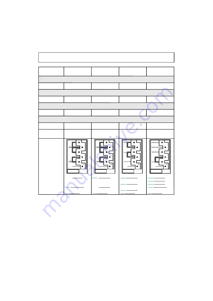
Connection

to term inal

board

Shunting:

m ake a

bridge with

shunt

L1:

Phase

Shunt     1-2 &

Shunt     2-3

N:

 Neutral

Shunt     4-5

E :

 Earth

L1:

 Phase

Shunt     1-2 &

Shunt     2-3

L2:

 Phase

Shunt     4-5

E :

 Earth

L1:

 Phase

Shunt      1-2

L2:

 Phase

Shunt      3-4

L3:

 Phase

   5

E:

 Earth

L1:

 Phase

  1

L2:

 Phase

  2

L3:

 Phase

  3

N:

 Neutral

Shunt     4-5

E:

 Earth

INSTALLATION – ELECTRICAL CONNECTION

1

2

3

4

5

T

L2

L1

1

2

3

4

5

T

L1

L2

L3

1

2

3

4

5

T

L1

L2

L3

N

1

2

3

4

5

T

N

L1

Summary of Contents for PVD 604

Page 1: ...TICE D EMPLOI ET D INSTALLATION Tables Vitrocéramiques PT MANUAL DE UTILIZAÇÃO E DE INSTALAÇÃO Placas Vitrocerâmicas GB INSTRUCTIONS FOR USE AND INSTALLATION Ceramic hobs H PVD 604 H PVD 605 H PVD 756 44000035 ...

Page 2: ...e la table vitrocéramique 13 Activation d un foyer de cuisson 13 Arrêt d un foyer de cuisson 14 Arrêt général 14 Indicateur de chaleur résiduelle 14 Fonctionnement du foyer complémentaire 14 15 Programmation d un foyer de cuisson 15 Fonctionnement de la touche verrouillage 16 Fonctionnement de l accélérateur de chauffe 17 Entretien de la table vitrocéramique 18 19 Fiche Technique Informations tech...

Page 3: ...die LIRE ATTENTIVEMENT LA NOTICE POUR VOUS PERMETTRE DE TIRER LE MEILLEUR PARTI DE VOTRE TABLE Nous vous conseillons de conserver la notice d installation et d utilisation pour toute consultation ultérieure et de noter ci dessous avant installation de la table le numéro de série de l appareil en cas d éventuelle demande d intervention du service après vente Plaque signalétique située sous le caiss...

Page 4: ...ommateurs Dans ces conditions il est impératif de confier cette tâche à un profes sionnel qui la réalisera conformément aux normes techniques en vi gueur Si malgré cette recommandation le consommateur réalisait lui même l installation le Groupe Candy déclinerait toute responsabilité en cas de défaillance technique du produit entraînant ou non des dommages aux biens et ou aux personnes INSTALLATION...

Page 5: ...être installé de telle façon que la prise de courant soit accessible Le fil de protection vert jaune doit être relié aux bornes de terre de l appareil d une part et de l installation d autre part Notre responsabilité ne saurait être engagée pour tout incident ou ses conséquen ces éventuelles qui pourraient survenir lors de l usage d un appareil non relié à la terre ou relié à une terre dont la con...

Page 6: ...pérer les deux languettes situées sur les côtés placer la lame d un tournevis à l avant de chaque languette enfoncer et presser soulever le capot raccorder le câble d alimentation en respectant les indications du tableau page 7 et les marquages sur la plaque à borne mettre en place les barrettes shunts les barrettes shunts insérées dans la plaque à bornes permettent d établir un pont entre deux bo...

Page 7: ... 8 8 4 4 W Q 8 8 4 4 W Q 8 8 4 4 V P G O G J E P C T G W S C N R C N T W U U G P T Q D T G V P W J 5 V P Q R P W T K N D C V G P W F G F K C N V P W J U G V V G T T C D G U C J 2 V G T G V P W J 5 T G V P W J 5 0 G T V W G 0 T G V P W J 5 6 G T T G 6 G U C J 2 V G T G V P W J 5 T G V P W J 5 G U C J 2 T G V P W J 5 6 G T T G 6 G U C J 2 T G V P W J 5 G U C J 2 T G V P W J 5 G U C J 2 6 G T T G 6 G...

Page 8: ... le bas en prenant soin de protéger le verre placer le joint tout autour de la table veiller particulièrement à le placer correctement afin d éviter toute infiltration dans le meuble support Prévoir un espace de 5 cm minimum entre l appareil et les parois verticales avoisinan tes Si en fonction de l installation de la table la partie inférieure de son caisson se trouve à proximité d une zone norma...

Page 9: ...astrement de la table dans un meuble support Encastrement de la table au dessus d un four ventilé équipé d une turbine de refroidissement pour les organes électriques ouverture 10 X 10 cm pour le passage du cordon d alimentation 50 mm 10 mm 50 mm 10 mm mini Ouverture 500 X 50 Ouverture 500 X 10 Il est interdit d enchâsser un four non ventilé sous la table vitrocéramique ...

Page 10: ...604 High light 1200 W High light 1200 W High light 2300 W High light 1800 W PVD 605 High light 1200 W High light 2300 W High light 1000 1200 W High light 1200 W PVD 756 High light 1800 W High light 900 1500 W High light 1200 W High light 1000 1200 W ...

Page 11: ... les récipients les mieux adapté pour obtenir de bons résultats Inox conseillé Spécialement bon avec fond Sandwich Le fond Sandwich allie les qualités de l inox aspect durabilité et stabilité avec les avantages de l aluminium ou cuivre transmission de la chaleur et répartition uniforme Aluminium fond épais recommandé Bonne conductivité Les résidus d aluminium apparaissent quelquefois sous forme de...

Page 12: ...commandes avec voyant 9 Touche de commande du foyer complémentaire 10 Diode de fonctionnement de la zone complémentaire 11 Repère de programmation foyer lorsqu il s affiche il indique que le foyer est pris en charge par le minuteur 12 Diode de commande allumée le foyer ou la minuterie est actif une modification est possible éteinte le foyer ou la minuterie est figé sur la dernière information enre...

Page 13: ...er la touche ou pour choisir un niveau de puissance entre 1 et 9 è si vous appuyez sur la touche le niveau de puissance s affiche si vous appuyez sur la touche le niveau de puissance s affiche è En maintenant la pression sur la touche ou le niveau de puissance augmente ou diminue progressivement Les exemples suivants sont donnés à titre indicatif L expérience person nelle permet ensuite d adapter ...

Page 14: ...environ par l affichage suivant Pour les fins de cuisson nous conseillons d éteindre la zone de cuisson et de profiter de la chaleur résiduelle du foyer de cuisson pour terminer la cuisson en douceur Lorsque la température redescend en dessous de 60 C l affichage s efface N B après coupure de courant l indicateur de chaleur résiduelle disparaît définitive ment et ce même si la température de surfa...

Page 15: ...e affichée elle indique que le foyer est actif Appuyer sur la touche Minuterie Le répère de foyer autour de l affichage du minuteur rappelle le foyer commandé Appuyer sur la touche pour choisir une durée en minutes L enregistrement est automatique après trois secondes è le temps programmé peut être modifié à tout moment en réactivant la touche de sé lection du minuteur la diode de commande du minu...

Page 16: ...données de ce fait plus aucune autre touche n est accessible exceptée la touche Marche Arrêt Le voyant de verrouillage s allume è Pour stopper la fonction verrouillage il suffit de réappuyer sur la touche le voyant s éteint toutes les commandes sont à nouveau accessibles Si lors du verrouillage des commandes le minuteur est actif le temps sera décompté automati quement et coupera le foyer à la fin...

Page 17: ... Réduire si besoin à la position de chauffe souhaitée Position de Puissance libérée Durée d accélération Durée de fonction cuisson de chauffe minutes nement maxi avant coupure autom 0 0 0 0 H 1 3 1 6 H 2 6 3 6 H 3 11 5 5 H 4 16 6 5 5 H 5 19 8 5 4 H 6 32 2 5 1 5 H 7 45 3 5 1 5 H 8 65 4 5 1 5 H 9 100 0 1 5 H Ex Foyer de 1800 W à la position 6 puissance libérée 32 de 1800 W lorsque la fonction Accélé...

Page 18: ...r avec un chiffon doux ou papier essuie tout sec jusqu à ce que la surface soit nette Si après cet entretien courant des taches persistent disposer à nouveau quelques gouttes d un produit spécifique gratter à l aide d un grattoir en respectant un angle de 30 par rapport à la table jusqu à dispari tion des taches récalcitrantes essuyer avec un chiffon doux ou un papier essuie tout sec jusqu à que l...

Page 19: ...r avec lame de rasoir ne peut endommager la surface si un angle de 30 est respectée Ne pas laisser le racloir avec lame de rasoir à la portée des enfants Ne pas utiliser de produits abrasifs ou de poudres récurantes Le cadre de la table selon modèle Pour nettoyer sans endommager le cadre de votre table le laver avec du savon et de l eau rincer puis sécher avec un chiffon doux ...

Page 20: ...O P G T W G I T C T W G F P Q H Q T 2 T W G V W C G T T G X T W G U U K C R G W S K O C T E Q T V K X 5 4 1 6 0 5 5 7 2 G J E W C T I G T K T T 9 V J I K N J I K 9 V J I K N J I K 9 V J I K N J I K G J E W C I V P C X 9 V J I K N J I K V J I K N J I K 9 V J I K N J I K 9 V K Q T F G T K T T 9 V J I K N J I K 9 V J I K N J I K V J I K N J I K 9 V K Q T F V P C X 9 V J I K N J I K 9 V J I K N J I K ...

Page 21: ... rugueux sont utilisés des particules tels que grains de sable ou sel se trouvent entre la table et le fond du récipient Se reporter au chapitre ENTRETIEN s assurer que les fonds des récipients sont propres avant utilisation et n utiliser que des récipients avec fond lisse Les rayures peuvent être atténuées seulement si un bon nettoyage est réalisé Ne pas faire glisser des récipients en aluminium ...

Page 22: ...plus de 10 secondes au moins 2 touches la table se met en sécurité et un bip sonore fonctionne tant que les touches sont recouvertes Nettoyer le débordement ou retirer l objet Les foyers s arrêtent automatiquement si on les laisse fonctionner pendant une période assez longue Se reporter au chapitre Durée de fonctionnement page 17 Les cycles coupure fonctionnement varient en fonc tion du niveau de ...

Page 23: ... 23 ...

Page 24: ...des de ligação do aparelho 35 Activação de uma placa de cozedura 35 Desactivação de uma placa de cozedura 36 Desactivação geral 36 Indicação de calor residual 36 Funcionamento da placa complementar 36 Programação de uma placa de cozedura 37 Funcionamento da tecla de trancamento 38 Funcionamento do acelerador de aquecimento 39 Limpeza da placa vitrocerâmica 40 41 Ficha Técnica Informações técnicas ...

Page 25: ... LER ATENTAMENTE ESTE MANUAL PARA PODER TIRAR TODO O PARTIDO DO APARELHO Aconselhamos que este manual seja guardado para posterior consulta e que nele seja anotado antes da instalação do aparelho o respectivo número de série para os casos em que eventualmente seja necessário recorrer à intervenção do Serviço Após Venda Placa de identificação na parte inferior do aparelho O painel de comando da pla...

Page 26: ... dos seus utilizadores Assim sendo torna se imperativo confiar esta tarefa a um profissional para que a sua execução seja feita de acordo com as normas técnicas em vigor Se apesar deste aviso a instalação for feita por alguém não qualificado o Grupo Candy declina qualquer responsabilidade em caso de avaria técnica do produto quer provoque ou não danos materiais e ou pessoais INSTALAÇÃO AVISO ...

Page 27: ...eléctrica esta deve ficar acessível quando o aparelho for instalado Um dos lados do fio de protecção verde amarelo deve ser ligado aos bornes de terra do aparelho e o outro lado do fio à instalação Declinamos qualquer responsabilidade por acidentes ou pelas suas eventuais consequências em caso de não ligação à terra do aparelho ou por uma ligação à terra com deficiente continuidade Qualquer interv...

Page 28: ... as duas linguetas que se encontram nos lados com uma chave de fendas carregar na parte da frente de cada uma das linguetas levantar a tampa Ligar o cabo de alimentação respeitar as marcações da placa de bornes e as indicações do quadro da página 29 e aplicar as caixas de derivação as caixas de derivação inseridas na placa de bornes dão a possibilidade de se estabelecer uma ponte eléctrica entre d...

Page 29: ... O w O O w O O Q R K 6 W Q 8 8 4 4 W Q 8 8 4 4 W Q 8 8 4 4 W Q 8 8 4 4 Q µ C I K G F C E C N R U G P T Q D T C X K T G C O W T G C H O Q E Q µ C I K N G F C Z K C E Q µ C X K T G F G U C G T C X K T G T C X K T G 0 Q T V W G 0 T C X K T G 6 C T T G 6 G U C G T C X K T G T C X K T G G U C T C X K T G 6 C T T G 6 G U C T C X K T G G U C T C X K T G G U C 6 C T T G 6 G U C G U C G U C 0 Q T V W G 0 T...

Page 30: ...dro colocar a junta à volta da placa ter o cuidado de aplicar devidamente a junta para evitar infiltrações no móvel que lhe serve de suporte Deixar um espaço de 5 cm no mínimo entre o aparelho e as paredes verticais que lhe são próximas Se a parte inferior da caixa que forma o aparelho ficar próximo de uma zona a que se acede habitualmente para manipular e ou guardar objectos colocar quando se pro...

Page 31: ...75 mm 5 1 0 m m 5 1 0 m m INSTALAÇÃO ENCASTRAMENTO ABERTURA 10 X 10 cm Encastramento da placa Encastramento da placa por cima dum num móvel suporte forno ventilado com turbina de refrigeração para órgãos eléctricos É interdito o encastramento de um Forno Não Ventilado por debaixo da placa vitrocerâmica abertura abertura ...

Page 32: ...04 High light 1200 W High light 1200 W High light 2300 W High light 1800 W PVD 605 High light 1200 W High light 2300 W High light 1000 1200 W High light 1200 W PVD 756 High light 1800 W High light 900 1500 W High light 1200 W High light 1000 1200 W ...

Page 33: ...cção dos recipientes mais adequados de forma a obterem se os melhores resultados Inox aconselhado Especialmente com fundo sanduíche Este fundo alia as qualidades do inox aspecto durabilidade e estabilidade às vantagens do alumínio ou do cobre transmissão do calor e repartição uniforme Alumínio recomendado o fundo espesso Boa condutividade O alumínio deixa por vezes marcas na placa que desaparecem ...

Page 34: ...Tecla de comando da placa de cozedura complementar 10 Testemunho de funcionamento da placa complementar 11 Identificação de programação da placa de cozedura quando afixada indica que a placa de cozedura está sob controlo do conta minutos 11 Testemunho de comando aceso a placa de cozedura ou o conta minutos encontra se activo podem fazer se modificações apagado a placa de cozedura ou o conta minuto...

Page 35: ... torna se fixo o que indica que essa zona está ligada Pressionar a tecla ou para seleccionar o nível de potência entre 1 e 9 è Se pressionar a tecla aparece o nível de potência se pressionar a tecla surge afixado o nível de potência è Se se mantiver premida a tecla ou o nível de potência aumenta ou diminui progressivamente Os exemplos que se seguem são dados a título meramente indicativo A experiê...

Page 36: ...ravés da afixação do painel de comando No final da cozedura dos alimentos aconselhamos a desligar a placa e a aproveitar o seu calor residual para que o cozinhado possa terminar brandamente Logo que a temperatura baixa para menos de 60 C a afixação apaga se N B Após corte da corrente a indicação de calor residual desaparece definitivamente e o mesmo acontece quando a temperatura da superfície ultr...

Page 37: ...ível de potência deve ficar afixado indicando assim que a placa está ligada Pressionar a tecla do conta minutos A identificação da placa junto à afixação do conta minutos recorda qual a placa accionada Pressionar a tecla para seleccionar os minutos O registo é feito automaticamente ao fim de três segundos è O tempo programado pode ser modificado em qualquer momento voltando para tal a pressionar a...

Page 38: ...el a tecla ligar desligar pois todas as outras deixam de ficar operacionais O testemunho do trancamento acende se è Para anular o trancamento basta voltar a pressionar a tecla o testemunho apaga se e todos os comandos ficam novamente operacionais Se o conta minutos estiver activo quando os comandos são trancados no final do tempo programado o tempo será descontado automaticamente e a placa desliga...

Page 39: ...rio para a posição de aquecimento pretendida Posição de Potência libertada Duração de aceleração Duração de cozedura de aquecimento funcionamento máx minutos antes de esactivação automática 0 0 0 0 H 1 3 1 6 H 2 6 3 6 H 3 11 5 5 H 4 16 6 5 5 H 5 19 8 5 4 H 6 32 2 5 1 5 H 7 45 3 5 1 5 H 8 65 4 5 1 5 H 9 100 0 1 5 H Ex Placa de cozedura de 1800 W na posição 6 potência libertada 32 de 1800 W Quando o...

Page 40: ... um pano macio ou papel de cozinha secos até a superfície ficar limpa Se após esta limpeza corrente as manchas continuarem Aplicar novamente algumas gotas do produto próprio Raspar com um raspador mantendo um ângulo de 30º em relação à superfície até as manchas persistentes desaparecerem Se necessário lavar Limpar com um pano macio ou papel de cozinha secos até a superfície ficar limpa Repetir a o...

Page 41: ...ear for utilizado de forma a fazer um ângulo de 30º em relação à superfície não causará quaisquer danos Não deixar o raspador com a lâmina ao alcance de crianças Não utilizar produtos abrasivos ou pós que possam riscar Enquadramento da placa consoante o modelo Para limpar o enquadramento da placa sem o danificar lavá lo com água e sabão enxaguá lo e depois secá lo com um pano macio ...

Page 42: ... W H Q T 2 C T W V N Q F C T W U U G R U Q T F K X Q E K O T G E Q T V K X 4 7 1 5 2 5 0 6 1 2 C T K G U C T 6 C F T G W S U G 9 V J I K N J I K 9 V J I K N J I K 9 V J I K N J I K C T K G V P C K C F T G W S U G 9 V J I K N J I K V J I K N J I K 9 V J I K N J I K 9 C V K G T K F C T K G U C T 6 9 V J I K N J I K 9 V J I K N J I K V J I K N J I K 9 C V K G T K F C T K G V P C K 9 V J I K N J I K 9...

Page 43: ...o pelo menos igual ao da placa de cozedura Mau método de limpeza ou uso de recipientes com o fundo irregular podendo haver areia ou sal entre a placa e o fundo do recipiente Consultar o capítulo LIMPEZA Certificar se de que o fundo dos recipientes está limpo antes de os utilizar e usar apenas recipientes com fundo plano Os riscos só podem ser atenuados se for feita uma limpeza correcta Não arrasta...

Page 44: ...imento ou um objecto a tapar durante mais de 10 segundos duas teclas pelo que o sistema de segurança da placa vitrocerâmica foi accionado dando origem a um sinal sonoro Limpar o alimento que veio por fora ou retirar o objecto As placas de cozedura param automaticamente se forem deixadas a funcionar durante bastante tempo Consultar o capítulo Duração de funcionamento na página 39 Os ciclos de corte...

Page 45: ... 45 ...

Page 46: ...ls 56 Use Switching on the ceramic hob 57 Starting a cooking zone 57 Stopping a cooking zone 58 General stopping 58 Residual heat indicator 58 Operating the additional cooking zone 58 59 Programming a cooking zone 59 Locking button operation 60 Fast heater operation 61 Cleaning the ceramic hob 62 63 Data sheet Technical information 64 Problems and solutions Advice 65 66 CONTENTS ...

Page 47: ...mention the risks of fire propagation READ THE INSTRUCTIONS CAREFULLY TO MAKE THE MOST OF YOUR HOB We recommend you keep the instructions for installation and use for later reference and before installing the hob note its serial number below in case you need to get help from the after sales service Identification plate located under the hob s bottom casing The hob s control area is sensitive do no...

Page 48: ...his work must be entrusted to a professional who can carry it out in compliance with the technical standards in force However if despite this recommendation the consumer carries out the installation themself the Candy Group will not accept any responsibility in case of technical failure of the product whether or not it causes damage to goods and or persons INSTALLATION IMPORTANT NOTICE ...

Page 49: ...installed so that the socket outlet is accessible The green yellow protection wire must be linked to the earth terminals of the appliance on one side and the installation on the other side We cannot be held responsible for any incident or its consequences that may arise during the use of an appliance not linked to the earth or linked to an earth whose continuity is defective All work in relation t...

Page 50: ... the two tabs located on the sides put the blade of a flat screwdriver in front of each tab push in and press remove the cover Connect the power supply cable comply with the information of the table page 51 and the markings on the terminal board and install the shunts the shunts inserted in the terminal board make a bridge between two terminals strip the end of each conductor and attach them to th...

Page 51: ...05VV F or H05RR F H05VV F or H05RR F H05VV F or H05RR F H05VV F or H05RR F Connection to term inal board Shunting m ake a bridge with shunt L1 Phase Shunt 1 2 Shunt 2 3 N Neutral Shunt 4 5 E Earth L1 Phase Shunt 1 2 Shunt 2 3 L2 Phase Shunt 4 5 E Earth L1 Phase Shunt 1 2 L2 Phase Shunt 3 4 L3 Phase 5 E Earth L1 Phase1 L2 Phase2 L3 Phase3 N Neutral Shunt 4 5 E Earth INSTALLATION ELECTRICAL CONNECTI...

Page 52: ...ide down taking care to protect the glass place the seal all round the hob make sure it is placed correctly to prevent any ingress into the support unit Leave a gap of at least 5 cm between the appliance and any neighbouring vertical surfaces If according to the hob s installation the casing bottom is near a zone normally accessible during handling and or storage install a partition 1 cm from the ...

Page 53: ...5 1 0 m m INSTALLATION FITTING Fitting the hob in a support unit Fitting the hob above a ventilated oven equipped with a cooling fan for the electrical components opening 10 X 10 cm 50 mm 10 mm 50 mm 10 mm mini Ouverture 500 X 50 Ouverture 500 X 10 It is forbidden to fit the hob above a non ventilated oven Opening Opening ...

Page 54: ...ht 1200 W High light 1200 W High light 2300 W High light 1800 W PVD 605 High light 1200 W High light 2300 W High light 1000 1200 W High light 1200 W PVD 756 High light 1800 W High light 900 1500 W High light 1200 W High light 1000 1200 W ...

Page 55: ...ts Stainless steel advised Especially good with a Sandwich bottom The Sandwich bottom combines the qualities of stainless steel appearance long life and stability with the advantages of aluminium or copper heat transmission and uniform distribution Aluminium thick bottom recommended Good conductivity Warning sometimes aluminium residues appear as traces on the hob but they can be removed if cleane...

Page 56: ...dicator lamp 9 Additional cooking zone control button 10 Additional zone operational LED 11 Cooking zone programming indicator when displayed it shows that the timer controls the cooking zone 12 Control LED on the cooking zone or timer is active modification is possible off the cooking zone or timer is set to the last recorded data according to model TOUCH SENSITIVE CONTROLS ...

Page 57: ...It shows that the zone is live Press the or button to select a heat level between 1 and 9 è Press the button and heat level is displayed press the button and heat level is displayed è Hold down the or button and the heat level increases or decreases gradually The following examples are for information only Personal experience should then let you adapt these settings to your taste and habits 0 Off ...

Page 58: ...the following displaying For ending the cooking we advise switching off the cooking zone and using the residual heat of the zone to finish cooking gently When the temperature goes back below 60 C the display goes off N B After a cut in the current the residual heat indicator disappears completely even if the surface temperature exceeds 60 C OPERATING THE ADDITIONAL COOKING ZONE An additional cooki...

Page 59: ...ust be displayed it shows that the zone is live Press the Timer button The zone mark around the timer display shows the controlled zone Press the button to select the time in minutes This is saved automatically after three seconds è The programmed time can be modified at any moment by pressing the timer selection button the timer control LED must be on When the time has run the cooking zone goes o...

Page 60: ...this way no other button works except the On Off button The locking indicator lamp comes on è To release the locking function just press the button the indicator lamp goes off all the controls work again If when the controls are locked the timer is on the time will be counted automatically and the zone switched off at the end of the programmed time If the locking control is on when the hob is fina...

Page 61: ...ce to the required heat position Cooking Power Time of fast Maximum operating time position released heater minutes before automatic cut off 0 0 0 0 H 1 3 1 6 H 2 6 3 6 H 3 11 5 5 H 4 16 6 5 5 H 5 19 8 5 4 H 6 32 2 5 1 5 H 7 45 3 5 1 5 H 8 65 4 5 1 5 H 9 100 0 1 5 H E g 1800 W zone at position 6 32 of 1800 W power released When the Fast heater is on the zone supplies 1800 W power for 2 5 minutes a...

Page 62: ...cloth or kitchen roll until the surface is clean If stains remain after this usual cleaning Sprinkle a few more drops of special cleaner Use a scraper keeping it at an angle of 30 to the hob until the difficult marks go Wipe with dry soft cloth or kitchen roll until the surface is clean Repeat if necessary ADVICE Regular cleaning leaves an protective layer that is essential to prevent scratches an...

Page 63: ... razor blade scraper cannot damage the surface if it is used at an angle of 30 Do not leave the razor blade scraper within the reach of children Do not use abrasive cleaners or scouring powder The hob frame according to model To clean your hob s frame without harm wash it with soap and water rinse and then dry with a soft cloth ...

Page 64: ...H eight 55 55 55 Ceram ic glass thickness 4 4 4 CO O KING ZO NE POW ER AN D Ø Back left H igh light 1200 W Ø 155 H igh light 1200 W Ø 155 H igh light 1200 W Ø 155 Front left H igh light 2300 W Ø 220 H igh light 1000 1200 W Ø 155 220 H igh light 1000 1200 W Ø 140 215 Back right H igh light 1200 W Ø 155 H igh light 2300 W Ø 220 H igh light 900 1500 W Ø 180 275 Front right H igh light 1800 W Ø 185 H ...

Page 65: ... as the cooking zone Incorrect cleaning or rough bottomed pans are used particles like grains of sand or salt get between the hob and the bottom of the pan Refer to the CLEANING section make sure that pan bottoms are clean before use and only use smooth bottomed pans Scratches can be lessened only the cleaning is done correctly Do not slide aluminium pans on the hob Refer to the cleaning recommend...

Page 66: ...vers at least two buttons for more than 10 seconds the hob switches to safety and an audible beep sounds so long as the buttons are covered Clean up the spill or remove the object The cooking zones stop automatically if they are left on for too long Refer to the section Operating time page 61 The on off cycles vary according to the required heat level low level short operating time high level long...

Page 67: ... 67 ...

Page 68: ...68 CANDY ELETTRODOMESTICI S R L BRUGHERIO MILANO ITALIA ...

Reviews: