


3.2 Pipelines Connection
3.1 Installation Instruction
①
②
3. UNIT INSTALLATION
5
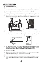
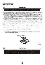
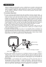
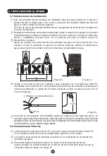
This electrical water heater shall be installed on a solid wall. If the strength of the wall cannot
bear the load equal to two times of the total weight of the heater filled fully with water, it is
then necessary to install a special support.
Incase of hollow bricks wall, ensure to fill it with cement concrete completely.
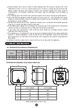
After selecting a proper location, install the mounting bracket to a solid wall.
Methods of installation: Follow the installation as shown in Fig.3. Use the anchors and
fasteners provided along with the product for securing the bracket(Fig.2) firmly in the wall.
Align the slots on the back of the water heater with the projections on the bracket and mount
the water heater on the bracket. Thereafter slide the water heater gently towards the bottom
side on lock the water heater.
⑤
If the bathroom is too small, the heater can be installed at another place without sun-scorched and
rain-drenched. However, in order to reduce the pipeline heat losses, the installation position of
the heater shall be closed to the location shall be as near as possible to the heater.
①
②
③
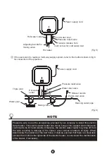
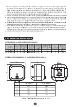
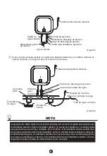
The dimension of each pipe part is G1/2” ; The massive pressure of inlet should use Pa as
the unit; The minimum pressure of inlet should use Pa as the unit.
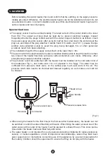
Connection of pressure relief valve with the heater on the inlet of the water heater.
In order to avoid leakage when connecting the pipelines, the rubber seal gaskets provided
with the heater must be added at the end of the threads to ensure leak proof joints (see
Fig.5).
(Fig.4)
④
Install the supply socket in the wall. The requirements for the socket are as follows: 250V/10A,
single phase, three electrodes. It is recommended to placed the socket on the right above
the heater. The height of the socket to the ground shall not be less than 1.8m (see Fig.4). If
there is fault on power cable, it should be replaced by the manufacturers, agencies or qualified
person who is able to do this so as to ensure the safety.
③
(Fig.2)
(Fig.3)
100
36
20
66
2-
Φ
8.5
2.2
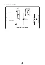
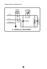
N (Blue)
L (Brown) E (Yellow/Green)
Ground
≥1.8m


