background image

VIO-PC100-EHL    

l

User’s Manual  

84

Chapter 5: BIOS Setup

Item 

Options 

Description 

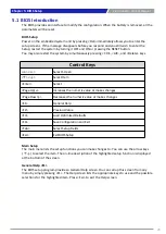
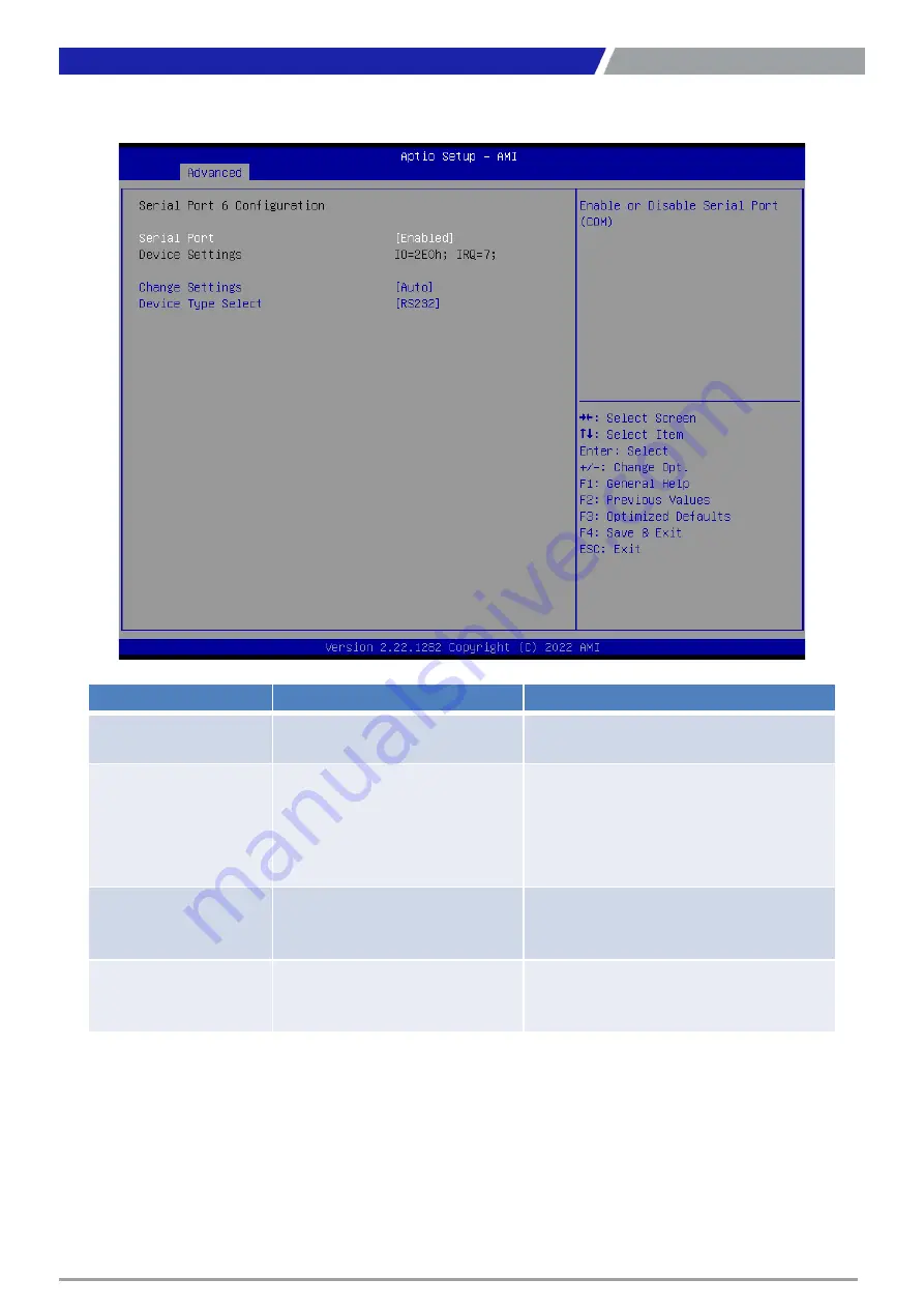
Serial Port 

Disabled,

Enabled

[Default]

Enable or Disable Serial Port (COM). 

Change Settings

Auto

[Default]

,

IO=2E0h; IRQ=7; ,

IO=3E8h; IRQ=3,4,5,6,7,9,10,11,12; ,

IO=2E8h; IRQ=3,4,5,6,7,9,10,11,12;,
IO=2F0h; IRQ=3,4,5,6,7,9,10,11,12;,

IO=2E0h; IRQ=3,4,5,6,7,9,10,11,12;

This item allows you to change the address & 
IRQ settings of the specified serial port.

Device Type Select

UART 232

[Default], 

UART 422, 

UART 485 

Set the Serial Port to RS232 & RS422 & RS485

RS-485 Auto Flow 

Function

Disabled,

Enabled

[Default]

Enabled/Disabled RS485 Autoflow Function

Serial Port 6 Configuration

Summary of Contents for VIO-200-PC100-EHL Series

Page 1: ...VIO 200 PC100 EHL Series VIO 100 PC100 EHL Series Industrial Panel PCs...

Page 2: ...10 PC100 EHL Series 22 1 4 2 VIO 212 PC100 EHL Series 23 1 4 3 VIO 215 PC100 EHL Series 24 1 4 4 VIO 217 PC100 EHL Series 25 1 4 5 VIO 219 PC100 EHL Series 26 1 4 6 VIO W215 PC100 EHL Series 27 1 4 7...

Page 3: ...3 10 Serial Port Console Redirection 89 5 3 11 USB Configuration 90 5 3 12 Network Stack Configuration 91 5 4 Chipset 92 5 4 1 System Agent SA Configuration 93 5 4 2 PCH IO Configuration 96 5 5 Secur...

Page 4: ...of this manual may be reproduced or transmitted in any form or by any means electronic or mechanical including photocopying recording or information storage and retrieval systems without the prior wr...

Page 5: ...the power outlet Disconnect this equipment from the power before cleaning Use a damp cloth Do not use liquid or spray detergents for cleaning Avoid the dusty humidity and temperature extremes Do not...

Page 6: ...erial number Description of your peripheral attachments Description of your software operating system version application software etc A complete description of the problem The exact wording of any er...

Page 7: ...nel PC 1 2 Panel Mount Kit 8 3 Screw Pack 1 VIO 219 PC100 EHL VIO 219 PC100 EHL 1E Item Description Q ty 1 VIO 219 PC100 EHL Series Panel PC 1 2 Panel Mount Kit 14 3 Screw Pack 1 VIO W221 PC100 EHL VI...

Page 8: ...2 1 XGA Capacitive Touch Thin Frame Panel PC with Intel Celeron Processor J6413 1x Universal I O Bracket 1x PCIe 15 XGA Thin Frame Panel PC Product Description VIO 215R PC100 EHL 15 XGA Resistive Touc...

Page 9: ...itive Touch Thin Frame Panel PC with Intel Celeron Processor J6413 1x Universal I O Bracket 1x PCIe 21 5 Full HD Thin Frame Panel PC Product Description VIO W221R PC100 EHL 21 5 Full HD Resistive Touc...

Page 10: ...del No Product Description 1 E09A06008 Adapter AC DC 12V 5A 60W with 3pin Terminal Block Plug 5 0mm Pitch SFICBL022 Power Cord 3 pin US Type 180cm 1 TPCD00002 Power Cord European Type 180cm 1 TPCD0000...

Page 11: ...Chapter 1 Product Introductions...

Page 12: ...3 Designed with flat surface IP 65 dust waterproof front panel and aluminum die casting front frame with rugged body structure it is a versatile I O connections and rugged reliability industrial panel...

Page 13: ...80 Full HD 400 700 1 0 17925 H x 0 17925 V 160 140 VIO W221 PC100 EHL VIO W221 PC100 EHL 1E 21 5 16 9 300 5000 1 0 248 H x 0 248 V 178 178 VIO W224 PC100 EHL VIO W224 PC100 EHL 1E 23 8 16 9 350 1000 1...

Page 14: ...on LAN and PXE Audio Codec Realtek ALC888S System Memory 1x 260 Pin DDR4 2400 2667 3200MT s SODIMM Max up to 32 GB BIOS AMI 128Mbit SPI BIOS TPM TPM 2 0 Watchdog Software Programmable Supports 1 255 s...

Page 15: ...B 3 2 Gen 2 10 Gbps 2x USB 2 0 DP 1x DisplayPort 1 2 4096 x 2160 60Hz HDMI 1x HDMI 2 0b 4096 x 2160 60Hz Optional Others 4x WiFi Antenna Holes 1x Power Switch 1x AT ATX Switch 1x Remote Power On Off 1...

Page 16: ...11ms Physical Model No Dimensions Weights Mounting Options VIO 110 PC100 EHL 300 W x 238 5 D x 64 7 H mm 5 42 kg VESA Mounting Holes 75 x 75mm 100 x 100mm VIO 110 PC100 EHL 1E 300 W x 238 5 D x 86 7 H...

Page 17: ...put with terminal block DisplayPort Used to connect a DisplayPort monitor 4x USB port Used to connect USB device LAN port Used to connect the system to a local area network Removable HDD Bay Used to i...

Page 18: ...m HDD LED Indicates the status of the hard drive Reset switch Press to reset the system Digital I O Terminal Block The Digital I O terminal block supports 8 digital input and 8 digital output Line out...

Page 19: ...th terminal block DisplayPort Used to connect a DisplayPort monitor 4x USB port Used to connect USB device LAN port Used to connect the system to a local area network Removable HDD Bay Used to inserts...

Page 20: ...ndicates the power status of the system HDD LED Indicates the status of the hard drive Reset switch Press to reset the system Digital I O Terminal Block The Digital I O terminal block supports 8 digit...

Page 21: ...VIO PC100 EHL l User s Manual 21 Chapter 1 Product Introductions These are mounting holes for VESA mount 75x75mm and 100x100mm 1 3 3 VESA Mounting Hole...

Page 22: ...VIO PC100 EHL l User s Manual 22 1 4 Mechanical Dimensions 1 4 1 VIO 110 PC100 EHL VIO 110 PC100 EHL 1E Chapter 1 Product Introductions Unit mm Unit mm...

Page 23: ...VIO PC100 EHL l User s Manual 1 4 2 VIO 212 PC100 EHL VIO 212 PC100 EHL 1E 23 Chapter 1 Product Introductions Unit mm Unit mm...

Page 24: ...VIO PC100 EHL l User s Manual Chapter 1 Product Introductions 24 1 4 3 VIO 215 PC100 EHL VIO 215 PC100 EHL 1E Unit mm Unit mm...

Page 25: ...VIO PC100 EHL l User s Manual 25 Chapter 1 Product Introductions 1 4 4 VIO 217 PC100 EHL VIO 217 PC100 EHL 1E Unit mm Unit mm...

Page 26: ...VIO PC100 EHL l User s Manual 26 1 4 5 VIO 219 PC100 EHL VIO 219 PC100 EHL 1E Chapter 1 Product Introductions Unit mm Unit mm...

Page 27: ...VIO PC100 EHL l User s Manual 1 4 6 VIO W215 PC100 EHL VIO W215 PC100 EHL 1E 27 Chapter 1 Product Introductions Unit mm Unit mm...

Page 28: ...VIO PC100 EHL l User s Manual 28 1 4 7 VIO W221 PC100 EHL VIO W221 PC100 EHL 1E Chapter 1 Product Introductions Unit mm Unit mm...

Page 29: ...VIO PC100 EHL l User s Manual 29 1 4 8 VIO W224 PC100 EHL VIO W224 PC100 EHL 1E Chapter 1 Product Introductions Unit mm Unit mm...

Page 30: ...Chapter 2 Switches and Connectors...

Page 31: ...Switch and Connector Locations 2 1 1 Top View LAN2 LAN1 USB2 USB1 DP1 HDMI1 DC_IN1 PWR_SW1 DIO MIC_IN1 LINE_OUT1 COM1 COM2 PWR_SW2 SIM1 SIM2 COM3 COM4 AT_ATX1 PCIE1 COM5 BZ1 COM6 SATA1 M2_KB CLR_CMOS...

Page 32: ...VIO PC100 EHL l User s Manual 32 2 1 2 Bottom View Chapter 2 Switches and Connectors SODMM1 MPCIE1 BAT1 SIG_OUT1 M2 KE RESET1...

Page 33: ...2 and 2 0 SIM1 SIM2 SIM Card Socket COM1 COM6 RS232 RS422 RS485 Connector LAN1 LAN2 LAN Port DC_IN1 3 pin DC 9 36V Power Input Connector DP1 DisplayPort Connector LINE_OUT1 Line out Jack MIC_IN1 Mic...

Page 34: ...DI3_P 10 LAN2_MDI3_N L1_1 LAN2_SPD_2500 L2_ L2 LINK1000J L3_1 V3 3A_LAN2 L4_1 LAN2_LINK_ACT Pin Signal 1 LAN1_MDI0_P 2 LAN1_MDI0_N 3 LAN1_MDI1_P 4 LAN1_MDI1_N 5 R5_CT 6 R6_CT 7 LAN1_MDI2_P 8 LAN1_MDI2...

Page 35: ...P5_P 6 USB2_P6_P 7 GND 8 GND Chapter 2 Switches and Connectors USB Port 2 0 USB Port 3 2 Gen 2 Pin Signal Pin Signal 1 V5A_USBP12 10 V5A_USBP12 2 USB2_P1_N 11 USB2_P2_N 3 USB2_P1_P 12 USB2_P2_P 4 GND...

Page 36: ...1_AUX _HDMI_DDCDAT 8 GND 18 DP1_HPD 9 DP1_TXN2 19 DP_PWR Return 10 DP1_TXP3 20 DP_PWR Chapter 2 Switches and Connectors Display Port High Definition Multimedia Interface Pin Signal Pin Signal 1 HDMI_T...

Page 37: ...NC 2 PWRBT_IN 3 NC 4 GND 5 NC 6 GND Chapter 2 Switches and Connectors Power Input DC 9 36V Power Button DIO Digital I O Pin Signal Pin Signal 1 IN1_1 2 OUT1_1 3 IN2_1 4 OUT2_1 5 IN3_1 6 OUT3_1 7 IN4_...

Page 38: ...UT_RIGHT 3 AGND 4 AGND 5 LINEOUT_LEFT Pin Signal 1 AGND 2 MIC_IN_R 3 AGND 4 AGND 5 MIC_IN_L Chapter 2 Switches and Connectors Line out Jack Mic in Jack COM1 RS232 RS422 RS485 Connector Pin Signal Pin...

Page 39: ...485 Connector COM4 RS232 RS422 RS485 Connector Pin Signal Pin Signal 1 NDCD4 6 NDSR4 2 NRXD4 7 NRTS4 3 NTXD4 8 NCTS4 4 NDTR4 9 NRI4 5 GND Pin Signal Pin Signal 1 NDCD2 6 NDSR2 2 NRXD2 7 NRTS2 3 NTXD2...

Page 40: ...r RS232 RS422 RS485 Connector PWR_SW2 Remote Power Switch Pin Signal Pin Signal 1 CM5_DCD 6 CM5_CTS 2 CM5_DSR 7 CM5_DTR 3 CM5_RXD 8 CM5_RI 4 CM5_RTS 9 GND 5 CM5_TXD Pin Signal Pin Signal 1 CM6_DCD 6 C...

Page 41: ...et ATX1 AT ATX Power Mode Switch Pin Signal Pin Signal 1 P_UIM_PWR 5 GND 2 P_UIM_RST 6 P_UIM_VPP 3 P_UIM_CLK 7 P_UIM_DATA 4 CD 8 COM Pin Signal Pin Signal 1 P1_UIM_VDD 5 GND 2 P1_UIM_RST 6 P1_UIM_VPP...

Page 42: ...3 3V B10 3 3V A11 PCIE_X4_RST B11 PCIE_X4_WAKE_N A12 GND B12 NC A13 CLKOUT_PCIE_P0 B13 GND A14 CLKOUT_PCIE_N0 B14 X4SLOT_PCIE_6_TX_P A15 GND B15 X4SLOT_PCIE_6_TX_N A16 X4SLOT_PCIE_6_RX_P B16 GND A17...

Page 43: ...Rx 30 USIM1_RST 31 PERp1 USB3 0 Rx 32 USIM1_CLK 33 GND 34 USIM1_DATA 35 PETn1 USB3 0 Tx 36 USIM1_VDD 37 PETp1 USB3 0 Tx 38 DEVSLP O 39 GND 40 USIM2_DET 41 PERn0 SATA B 42 USIM2_DATA 43 PERp0 SATA B 4...

Page 44: ...VIO PC100 EHL l User s Manual 44 CLR_CMOS1 BZ1 Switch Signal On Clear CMOS Off Default Pin Signal 1 Positive 2 Negative Chapter 2 Switches and Connectors Clear BIOS Switch Buzzer...

Page 45: ...14 UIM_RESET 15 GND 16 UIM_VPP 17 Reserved 18 GND 19 Reserved 20 Reserved 21 GND 22 PERST 23 PERn0 24 3 3Vaux 25 PERp0 26 GND 27 GND 28 1 5V 29 GND 30 SMB_CLK 31 PETn0 32 SMB_DATA 33 PETp0 34 GND 35...

Page 46: ...Display Module Connector Pin Signal Pin Signal 1 PE1_TX 26 PE3_RX 2 PE1_TX 27 GND 3 GND 28 GND 4 GND 29 PE4_TX 5 PE1_RX 30 PE4_TX 6 PE1_RX 31 GND 7 GND 32 GND 8 GND 33 PE4_RX 9 PE2_TX 34 PE4_RX 10 PE...

Page 47: ...TCH 28 NOTCH 29 NOTCH 30 NOTCH 31 NOTCH 32 NC 33 NOTCH 34 NC 35 PCIE_1_TX_DP 36 NC 37 PCIE_1_TX_DN 38 NC 39 GND 40 NC 41 PCIE_1_RX_DP 42 NC 43 PCIE_1_RX_DN 44 NC 45 GND 46 NC 47 CLKOUT_PCIE_P1 48 NC 4...

Page 48: ...Chapter 3 Front Panel Controls...

Page 49: ...ion 2 Scrolls the OSD menu upward 3 Increases the value of a selected function Decrease Button 1 Activates the Volume control menu and decreases volume with audio option 2 Scrolls the OSD menu downwar...

Page 50: ...item allows you to on or off the Gamma function SuperResolution This setting allows you to select options for the SuperResolution Select Off Weak Median or Strong 3 2 2 Picture Phase Adjust the monit...

Page 51: ...anges the viewing position of the OSD menu to the left or right area of the screen Vertical Changes the viewing position of the OSD menu to the top or bottom area of the screen Transparency Adjust to...

Page 52: ...Chapter 4 System Setup...

Page 53: ...l you hear a click Ensure the memory card is secure before replacing the cover 4 1 Set torque force to 3 5 kgf cm to execute all the screwing and unscrewing 4 2 Installing SODIMM 53 Chapter 4 System S...

Page 54: ...card mSATA M 2 E Key 1 Two mini PCIe slots with M 2 E Key Support is available on PC100 Series 2 Insert mini PCIe card mSATA module at a 45 degree angle 3 Press the mini PCIe card or mSATA module dow...

Page 55: ...ed circle below and pull the tray towards you to remove the SATA HDD SSD bay 2 Unlock the drive lock by lifting the plastic insert up then insert the HDD SSD card 3 Once the HDD SSD card is inserted p...

Page 56: ...4 5 Installing SIM card 1 There are two SIM card slots are available on system chassis located next to the removable HDD bay as shown below 2 Place the SIM card inside the SIM slot until you hear a cl...

Page 57: ...y SIM 2 Mini PCIe mSATA M 2 B Key MiniPCIE1 mSATA 3 Please refer to the table below to note which SIM slot to insert your SIM card into according to the matching Mini PCIe type 4 To remove the SIM car...

Page 58: ...Setup 4 6 Removing chassis top cover 1 To remove the chassis top cover there are 6 screws to be unscrewed at the locations highlighted by the red circles below 2 Once all six screws are removed the c...

Page 59: ...ews located at the back of the system as pictured below The screw locations are highlighted in red 2 Remove 4 screws located at the front and side face of the system as pictured below The screw locati...

Page 60: ...he cable around the gap between the iron piece and the motherboard and connect it to the communication module 5 Put on washer and fasten the nut with antenna jack as indicated below 6 Fasten the 5 scr...

Page 61: ...er s Manual 61 7 Fasten the 4 screws located at the front and side face of the system as pictured below The screw locations are highlighted in red 8 Assemble the antenna and antenna jack together Chap...

Page 62: ...sis top cover 1 Ensure thermal pad is in place on the CPU thermal block 2 Close the chassis top cover following the below direction and make sure the aluminum part on the top cover is touching the the...

Page 63: ...VIO PC100 EHL l User s Manual 63 Chapter 4 System Setup 3 Fasten the 6 screws to lock the system body with top cover The locations are highlighted by the red circles below...

Page 64: ...PC module with its connector facing the back of VIO display module as shown in the picture below 2 Ensure the PC Module is aligned with the VIO Display Module and push it down gently 3 Screw the PC M...

Page 65: ...r s Manual 65 Chapter 4 System Setup 4 10 PC100 EHL 1E Installing PCIe expansion card 1 Unscrew the 6 screws indicated at the circles in the photos below 2 Once unscrewed remove the top cover of PC mo...

Page 66: ...rew the 3 screws below indicated at the locations highlighted below 4 Then unscrew the screw indicated in the red circle below 5 Attach the PCIe expansion card and then fasten the screw in the circle...

Page 67: ...stall the PCIe PCI card according to direction indicated in the picture below 7 Ensure the gold fingers are inserted properly into the slot 8 Fasten the 3 screws indicated at the locations in the red...

Page 68: ...68 Chapter 4 System Setup 9 Replace the chassis top cover and make sure the aluminum part on the top cover is touching the thermal pad on CPU thermal block 10 Fasten the 6 screws indicated by the red...

Page 69: ...Chapter 5 BIOS Setup...

Page 70: ...functions you can make changes to You can use the arrow keys to select the item The on line description of the highlighted setup function is displayed at the bottom of the screen General Help F1 The B...

Page 71: ...ain setup screen is showed as following when the setup utility is entered System Date Time is set up in the Main Menu System Date Set the system date Please use Tab to switch between data elements Sys...

Page 72: ...VIO PC100 EHL l User s Manual 5 3 Advanced Setup 72 Chapter 5 BIOS Setup...

Page 73: ...enabled a VMM can utilize the additional hardware capabilities provided by Virtualization Technology Active Processor Cores All Default 1 2 3 Number of cores to enable in each processor package C sta...

Page 74: ...VIO PC100 EHL l User s Manual 5 3 2 PCH FW Configuration 74 Chapter 5 BIOS Setup...

Page 75: ...abled Enabled Default Enable or Disable SATA Port Hot Plug Disabled Enabled Default Designates this port as Hot Pluggable SATA Device Type Hard Disk Drive Default Solid State Drive Identify the SATA p...

Page 76: ...Disable BIOS support for security device O S will not show Security Device TCG EFI protocol and INT1A interface will not be available Pending operation None Default TPM Clear Schedule an Operation for...

Page 77: ...led Default Enables or Disables System ability to Hibernate OS S4 Sleep State This option may not be effective with some operating systems ACPI Sleep State Suspend Disabled S3 Suspend to RAM Default S...

Page 78: ...ult Minute Mode Select Second Mode or Minute Mode Watch Dog Timer Time out Value 20 255 Second Default 1 255 Minute Watch Dog Timer Time out Value Item Description Serial Port 1 Configuration Set Para...

Page 79: ...7 9 10 11 12 IO 2F8h IRQ 3 4 5 6 7 9 10 11 12 IO 3E8h IRQ 3 4 5 6 7 9 10 11 12 IO 2E8h IRQ 3 4 5 6 7 9 10 11 12 This item allows you to change the address IRQ settings of the specified serial port De...

Page 80: ...8h IRQ 3 IO 3F8h IRQ 3 4 5 6 7 9 10 11 12 IO 2F8h IRQ 3 4 5 6 7 9 10 11 12 IO 3E8h IRQ 3 4 5 6 7 9 10 11 12 IO 2E8h IRQ 3 4 5 6 7 9 10 11 12 This item allows you to change the address IRQ settings of...

Page 81: ...7 9 10 11 12 IO 2E8h IRQ 3 4 5 6 7 9 10 11 12 IO 2F0h IRQ 3 4 5 6 7 9 10 11 12 IO 2E0h IRQ 3 4 5 6 7 9 10 11 12 This item allows you to change the address IRQ settings of the specified serial port De...

Page 82: ...7 9 10 11 12 IO 2E8h IRQ 3 4 5 6 7 9 10 11 12 IO 2F0h IRQ 3 4 5 6 7 9 10 11 12 IO 2E0h IRQ 3 4 5 6 7 9 10 11 12 This item allows you to change the address IRQ settings of the specified serial port De...

Page 83: ...7 9 10 11 12 IO 2E8h IRQ 3 4 5 6 7 9 10 11 12 IO 2F0h IRQ 3 4 5 6 7 9 10 11 12 IO 2E0h IRQ 3 4 5 6 7 9 10 11 12 This item allows you to change the address IRQ settings of the specified serial port De...

Page 84: ...7 9 10 11 12 IO 2E8h IRQ 3 4 5 6 7 9 10 11 12 IO 2F0h IRQ 3 4 5 6 7 9 10 11 12 IO 2E0h IRQ 3 4 5 6 7 9 10 11 12 This item allows you to change the address IRQ settings of the specified serial port De...

Page 85: ...S Setup 5 3 7 Hardware Monitor These items display the current status of all monitored hardware devices components such as voltages and temperatures Item Options Description Smart Fan Function Disable...

Page 86: ...m Options Description Fan1 SmartFan Control Manual Duty Mode Auto Duty Cycle Mode Default Smart Fan Mode Select Temperature 1 4 1 100 Auto fan speed control SMART FAN IV Duty Cycle 1 4 20 100 Auto fan...

Page 87: ...will not control IGN Module Write IGN BIOS will write setting to IGN module Power On Delay 10 Sec Default 20 Sec 30 Sec 40 Sec 50 Sec 1 Min Manual Mode Power On Delay Select Manual Mode 10 Sec Defaul...

Page 88: ...n sec specified Select DynamicTime System will wake on the current time Increase minute s Bypass BIOS will not control RTC wake function during system shutdown Wake up day 0 Default Date of month Alar...

Page 89: ...User s Manual 5 3 10 Serial Port Console Redirection 89 Chapter 5 BIOS Setup Item Options Description Console Redirection Disabled Default Enabled These items allows you to enable or disable COM1 cons...

Page 90: ...XHCI ownership change should be claimed by XHCI driver USB Mass Storage Driver Support Disabled Enabled Default Enable Disable USB Mass Storage Driver Support USB transfer time out 1 sec 5 sec 10 sec...

Page 91: ...support If disabled IPv4 PXE boot support will not be available IPv6 PXE Support Disabled Default Enabled Enable Disable IPv4 PXE boot support If disabled IPv6 PXE boot support will not be available P...

Page 92: ...IO PC100 EHL l User s Manual 5 4 Chipset This section allows you to configure and improve your system and allows you to set up some system features according to your preference 92 Chapter 5 BIOS Setup...

Page 93: ...apter 5 BIOS Setup Item Options Description VT d Disabled Enabled Default VT d capability Above 4GB MMIO BIOS assignment Enabled Default Disabled Enable Disable above 4GB MemoryMappedIO BIOS assignmen...

Page 94: ...Item Options Description Max TOLUD Dynamic Default 1GB 1 25GB 1 5 GB 1 75 GB 2 GB 2 25 GB 2 5 GB Maximum Value of TOLUD Dynamic assignment would adjust TOLUD automatically based on largest MMIO length...

Page 95: ...feature please disable CSM Support PSMI SUPPORT Disabled Default Enabled PSMI Enable Disable DVMT Pre Allocated 32M 64M 96M 128M 160M 4M 8M 12M 16M 20M 24M 28M 32M F7 36M 40M 44M 48M 52M 56M 60M Defa...

Page 96: ...te Specify what state to go to when power is re applied after a power failure G3 state M 2 B Key Selection USB PCIe x1 Default PCIe x2 Selects M 2 B KEy function PCIe x2 or USB PCIe x1 PCIe Port Selec...

Page 97: ...VIO PC100 EHL l User s Manual 97 Chapter 5 BIOS Setup PCI Express Configuration...

Page 98: ...Disabled Default L0s L1 L0sL1 Auto Set the ASPM Level Force L0s Force all links to L0s State AUTO BIOS auto configure DISABLE Disables ASPM PCIe Speed Auto Default Gen1 Gen2 Gen3 Configure PCIe speed...

Page 99: ...Chapter 5 BIOS Setup Item Options Description HD Audio Disabled Enabled Default Control Detection of the HD Audio device Disabled HDA will be unconditionally disabled Enabled HDA will be unconditional...

Page 100: ...5 BIOS Setup 5 5 Security Security menu allow users to change administrator password and user password settings Administrator Password This item allows you to set Administrator Password User Password...

Page 101: ...e if Secure Boot is Enabled Platform Key PK is enrolled and the System is in User mode The mode change requires platform reset Secure Boot Mode Standard Custom Default Secure Boot mode options Standar...

Page 102: ...Manual 102 Chapter 5 BIOS Setup Item Options Description Factory Key Provision Disabled Default Enabled Install factory default Secure Boot keys after the platform reset and while the System is in Set...

Page 103: ...65535 0xFFFF means indefinite waiting Bootup NumLock State On Default Off Select the Keyboard NumLock state Full Screen Logo Show Disabled Default Enabled Enables or disables Full Screen Logo Show opt...

Page 104: ...item allows user to reset the system after saving the changes This item allows user to reset the system after saving the changes Discard Changes and Reset This item allows user to reset the system wit...

Page 105: ...Appendix WDT GPIO This appendix provides the sample codes of WDT Watch Dog Timer and GPIO General Purpose Input Output...

Page 106: ...ode IO Address 0xA16 is time value IO Address 0xA15 is WDT enable and configuration Example Set 0xA16 0x03 0xA15 0x31 it will reset after 3 seconds define TimePort 0xA16 define TimeEnablePort 0xA15 Wr...

Page 107: ...dByte GPI_ADDR Read current Pin Status Offset 0xA02h default setting is 0x5F output pin set to output high at IO_DO1 Bit0 IO_DO8 Bit7 ByteData 0xFF set IO_DO1 IO_DO8 to high WriteByte GPO_ADDR ByteDat...

Page 108: ...Copyright C T Solution Inc All Rights Reserved www candtsolution com...

Reviews: