


11
REMOVAL AND REPLACEMENT OF PARTS
Before removing appliance case, isolate
the gas and electrical supplies. Isolate
boiler from the system and drain before
removing any component in the water-
ways. Ensure that the appliance is cool.
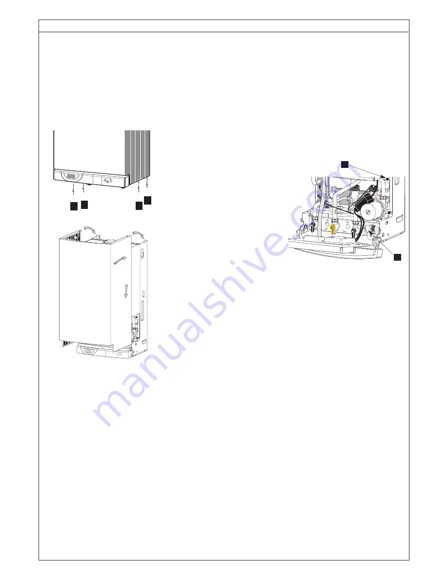
1. Outer Case
Remove four screws in base of case and
lift free. When replacing, carefully locate
on lugs T on top edge of chassis.
2. Sealed chamber front panel
Unscrew four self taping screws secur-
ing the sealed chamber front panel and
lift over top corner locating lugs.
Reassemble in reverse order.
3. Combustion Chamber front panel
and air/gas connection
Carry out step 1 and 2 as above.
Unscrew three screws securing the
air/gas connection pipe onto the gas
valve assembly. Disconnect Ionisation
and lighting electrodes from their wiring.
Unscrew six nuts to release combustion
chamber front panel and pull the assem-
bly towards you. Reassemble in reverse
order.
4. Ionisation electrode
Carry out step 1 and 2 as above.
Disconnect ionisation electrode from its
wiring. Loosen the 2 screws and pull it
out from the combustion chamber front
panel. Replace the ionisation gasket
provided. Reassemble in reverse order
5. Lighting electrode
Carry out step 1 and 2 as above.
Disconnect lighting electrode from its
wiring. Loosen the 2 screws and pull it
out from the combustion chamber front
panel. Replace the ionisation gasket
provided. Reassemble in reverse order.
6. Burner
Carry out step 1, 2 and 3 as above.
Remove the 4 Philips screw retaining the
burner onto the combustion chamber.
Pull it out with care to avoid any damage
to the ceramic panel protecting the com-
bustion chamber front panel. Replace
the burner gasket. Reassemble in
reverse order.
7. Gas vale assembly
Carry out step 1 and 2 as above.
Unscrew three screws securing the
air/gas connection pipe onto the gas
valve assembly. Disconnect the connec-
tors from gas solenoids and fan. Loosen
the gas pipe nut. Unscrew six nuts to
release combustion chamber front panel
and pull the assembly towards you.
Replace gas filter before fitting the full
assembly back in the boiler.
8. Fan assembly
Carry out all operations mentioned in
step 7. Unscrew the three screws secur-
ing the air/gas connection pipe onto the
gas valve assembly. Separate the gas
valve assembly and the venturi from the
fan assembly by loosen the two hexago-
nal head screws. Reassemble in reverse
order and replace the necessary gas-
kets.
9. Gas section
Carry out all operations mentioned in
step 7. Unscrew the three screws secur-
ing the air/gas connection pipe onto the
gas valve assembly. Separate the gas
valve assembly and the venturi from the
fan assembly by loosen the two hexago-
nal head screws. The venturi and the
gas section can be separated loosing
the 2 screw located at the top of the gas
valve. Replace necessary gaskets
before reassemble in reverse order.
10. Venturi in the gas section
Carry out all operations mentioned in
step 7. Unscrew the three screws secur-
ing the air/gas connection pipe onto the
gas valve assembly. Separate the gas
valve assembly and the venturi from the
fan assembly by loosen the two hexago-
nal head screws. The venturi and the
gas section can be separated loosing
the 2 screw located at the top of the gas
valve. Replace necessary gaskets
before reassemble in reverse order.
11. Drain down
2 drain points are located on the boiler
.
1 = Air separator
2 = Heating circuit drain point
12. Water filter
The C/H filter is located in the right
hydraulic assembly. Remove the return
pipe as described previously and with-
draw the filter. Reassemble in reverse
order.
13. Flow switch
Drain boiler as in step 11. Disconnect
the electrical plug, turn the top cover
anti-clockwise, remove the O-ring and
the brass piston. Reassemble in reverse
order.
A A
A
A
T
T
1
2
1
2