M U L T I - P U R P O S E A P P L I C A T I O N B O A R D S F O R D M S - 2 0 M E T E R S
DMS-EB2
MPM_DMS-EB2_D00
Page 3 of 4
D I G I T A L P A N E L M E T E R S
www.cd4power.com
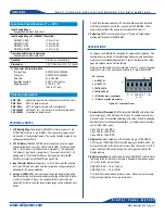
Figure 3. Installing U1
Figure 4. Installing R1
SG10
12
R3
R1
To measure input voltages
greater than ±100Vdc,
these two etch paths.
open SG10 and also cut
SG1
SG2
SG3
1
U1
TO-3-style tab
points to left
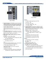
4. Calibration Adjustment:
The DMS-EB2 has provisions for adjusting the
calibration of the DMS-20 meter. Calibration adjustment is useful when
an input divider (using R1 and R2) is necessary to scale the input voltage.
The calibration potentiometer allows "tweaking" of the display reading.
Using the calibration potentiometer
Adjust the calibration pot on the back of the meter as desired. The
adjustment range is only 3/4 of a turn. Do not force the pot past its end
stops.
5. Differential Input Signals
(Signal Referenced to Power Source): Open
SG5. Apply the input signal to pin 1, (+) IN HI, and pin 2, (–) IN LO, of J1.
NOTE:
Common mode voltage must not exceed ±2Vdc.
6. Measuring Input Voltages Greater than 1.999Vdc
(Use DMS-20PC/
LCD-1 Only):
CAUTION:
Do not exceed 250Vdc input signal.
1. Open SG10. For applications in which input voltages exceed ±100Vdc,
also cut the 2 adjoining traces.
2. Calculate values for R1 and R2 as follows:
R2 = (FSI x R1) / ( |V
IN
| - FSI)
Where:
FSI = The attenuated voltage, between the meter's (–) IN LO and (+) IN
HI pins, needed to achieve the desired display readings
V
IN
= Input voltage at J1 (beween pins 1 and 2)
A typical value for R1 is 1M
Ω
. The sum of R1 + R2 should be
between 50k
Ω
and 10M
Ω
.
3. Enable DP3 by soldering SG3.
4. Calibrate the meter using a known voltage source. Adjust the internal
gain potentiometer to compensate for variations in R1 and R2.
Example
V
IN
is 199.9Vdc, and the display reading must be "199.9".
1. Assume R1 = 1.0M
Ω.
2. R2 = (FSI x R1) / ( |V
IN
| - FSI)
R2 = (1.999 x 1,000,000) / (199.9 - 1.999)
R2 = 10101.01
Ω
or 10k
Ω
7. Current Measurements
(Use 200mV Model, DMS-20PC/LCD-0): The
following instructions are for measuring current derived from the DMS-
20PC/LCD's power source. When measuring current that is floating with
respect to J1, pin 6 (GROUND), leave SG5 closed.
CAUTION:
Do not exceed 1 Ampere input current.
1. Install R2 (R2 = FSR / (I
MAX
x 10000)) where FSR is the
desired reading (0-1999) and I
MAX
is between 0 -1 Ampere.
2. Open SG5.
3. Apply input signal (current) to (+)IN HI and (–) IN LO.
4. Adjust internal gain pot for desired full scale readings.
5. Enable decimal points using either SG1, SG2 or SG3.
Example
A 1.0 Ampere input must read "1.000" on the display.
R2 = 1000 / (1 x 10000)
R2 = 0.1 Ohm
Enable DP1 via SG1 for reading of 1.000
8. Displaying DMS-20PC/LCD's Power Source
(Use DMS-20PC/LCD-2, 5V-Powered Models Only):
1. If the power source is higher than 5Vdc, be sure to install U1 and cut
SG4. See Battery Operation section and Technical Note 4.
2. Solder a short piece of jumper wire across the two holes labeled J2.
3. Close SG2 to enable DP2.


