


3. Installation
3. Installation
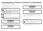
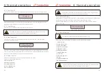
1). Connect the three (3) AC conductors to the three (3) AC terminals marked “L1”, “L2” and
“L3”.Refer to local code and voltage drop tables to determine the appropriate wire size
and type.
2). Connect the grounding conductor to the terminal marked “PE” (protective earth, the
ground terminal).
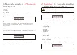
Over-Current Protection Device (OCPD) for the AC side
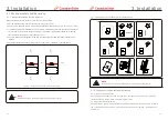
To protect the inverter's AC connection line, we recommend installing a device for protection
against over-current and leakage, with the following characteristics noted in Table 3.2:
3.6 Making connections to the AC side of the inverter
WARNING
An over-current protection device must be used between the inverter and
the grid.
Inverter
CSI-50KTL-GS-FLB
CSI-50KTL-GS-B
CSI-60KTL-GS-B
CSI-66KTL-GS-B
Rated voltage(V)
480V
480V
480V
480V
Rated output
power (kW)
50
50
60
66
Current rating for
protection device (A)
80
80
90
100
Table3.2 Over-current protection device characteristics for Canadian solar inverters
3.6.1 Connecting the inverter to the utility grid
All electrical installations must be carried out in accordance with the local standards and
the National Electrical Code® ANSI/NFPA 70 or the Canadian Electrical Code® CSA C22.1.
The AC and DC electric circuits are isolated from the enclosure. If required by section 250
of the National Electrical Code®, ANSI/NFPA 70, the installer is responsible for grounding
the system.
The grid voltage must be within the permissible range. The exact operating range of the
inverter is specified in Section 9 “Specifications”.
NOTE
Use AL-CU transfer (bi-metallic) terminal or
anti-oxidant
grease
with
aluminum
cables
and
terminals.
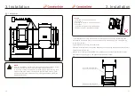
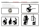
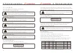
3.6.2 Wiring procedure
1). Insert the conduit fitting into the opening and tighten the
counter
nut.
2). Attach the conduit to the fitting in the enclosure opening.
3). Insert the AC cable through the conduit into the inverter.
CAUTION
RISK OF ELECTRIC SHOCK.
Prior to starting the wiring procedure, ensure
that the three-pole circuit breaker is switched off and cannot be reconnected.
NOTE
Damage or destruction of the inverter's electronic components due to
moisture and dust intrusion will occur if the enclosure opening is enlarged.
CAUTION
Risk of fire if two conductors are connected to one terminal. If a
connection of two conductors to a terminal is made, a fire can occur.
NEVER CONNECT MORE THAN ONE CONDUCTOR PER TERMINAL.
NOTE
Use M6 crimp terminals to connect to the inverter AC terminals
.
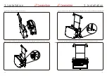
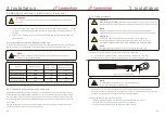
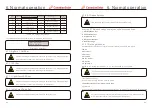
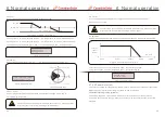
A)
If using multi conductor cables, strip the end of AC cable outer insulating
jacket about 3 inches. Strip the end of each wire . (as shown in figure 3.13)
The steps to assemble the AC grid terminals are listed as follows:
L2
L1
Figure 3.13 Strip AC cable
NOTE
L2 (insulation stripping length) is 1/8 inch longer than
L1 (OT cable terminal crimping area)
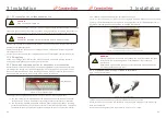
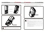
B) Strip the insulation of the wire past the cable crimping area of the OT terminal,
then use a hydraulic crimp tool to crimp the terminal. The crimped portion of the terminal
must be
insulated with heat shrinkable tube or insulating tape.
Connect the cable to grid terminal as below:
.25.
.24.


