background image

Controllers Area Networks Inc. 


Smart Tweezers User Manual Version 1.0 

Page 5 of 16 

Quick Reference 


Display Area 

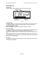
Smart Tweezers has two display modes, Primary and Secondary.


R=     20.03K

10 kHz

C  750.33 pF

PRIMARY DISPLAY

SECONDARY DISPLAY

BAR GRAPH


Figure 2. 


Primary Display 
The Primary Display is located in the middle of the display and is the larger of the 
two displays available. It shows the present reading. For most functions the 
primary display shows 5 digits.  
If 

OUT OF RANGE

 is displayed an overload condition is present. 

 
Secondary Display 
The Secondary Display is located at the top of the display and is the smaller of the 
two displays. It shows the present reading of additional parameters, or 
measurement conditions when the primary display shows some other feature (e.g. 
L, C).    
When multiple features are present, secondary display shows one of the values.  
For example, ESR value can appear in the secondary display while capacitor value 
appears in the primary display. 


Bar Graph 
The bar graph provides an analog indication of the measured input and is located 
at the bottom of the display. 

Summary of Contents for Smart Tweezers

Page 1: ...Area Networks Inc Smart Tweezers User Manual Version 1 0 Page 1 of 16 Controllers Area Network Inc Smart Tweezers User Manual Version 1 0 This Device Invented Developed and Manufactured in CANADA Pat...

Page 2: ...not use the device if it operates abnormally Do not attempt to measure any components in circuit when your circuit is under the power Cautions To avoid possible damage to Smart Tweezers or to the equi...

Page 3: ...tton 6 Virtual Ground 6 Slide Switch 6 Using the Smart Tweezer 7 Turning Smart Tweezers ON 7 Automatic Power Off 7 Battery 7 Low Battery Indication 7 Menu Structure 8 Changing from the Default Setting...

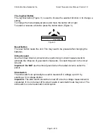
Page 4: ...n Virtual Ground Connector Reset Slide switch for extended Voltage measurements Figure 1 Smart Tweezers has a unique mechanical and electronic design that incorporates a built in direct precision SMD...

Page 5: ...y shows 5 digits If OUT OF RANGE is displayed an overload condition is present Secondary Display The Secondary Display is located at the top of the display and is the smaller of the two displays It sh...

Page 6: ...er changing the batteries Virtual Ground Use the Virtual Ground connector when performing in circuit measurements to eliminate the influence of grounded components Connect this point to the circuit Gr...

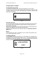
Page 7: ...uched or button pressed for approximately 30 seconds Pressing the Jog Dial button turns Smart Tweezers back on and the device then returns to the display for the previously selected function Automatic...

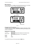
Page 8: ...CTUAL SETTING Figure 7 Changing from the Default Setting The Meter allows you to change the DEFAULT operating configuration of Smart Tweezers by changing the options All setup options affect general o...

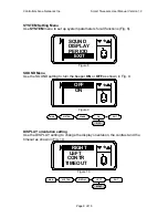
Page 9: ...SOUND DISPLAY PERIOD EXIT Figure 8 SOUND Menu Use the SOUND setting to turn the beeper ON or OFF as shown in Fig 9 c ON OFF Figure 9 MAIN SYSTEM SOUND ON OFF EXIT DISPLAY orientation setting Use the...

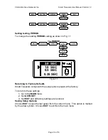
Page 10: ...YSTEM PERIOD 2 SEC 1 SEC 1 2 SEC 1 4 SEC EXIT c 0 25 SEC 1 0 SEC 0 5 SEC 2 0 SEC Figure 11 Returning to Factory Defaults Smart Tweezers comes with the setup options preset at the factory To return to...

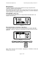
Page 11: ...ure a specific parameter or need better accuracy MEASUREMENT setting menu To measure specific components or to change measurement parameters use Measure menu Fig 12 c MODE FREQ VOLTAGE EXIT Figure 12...

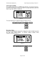
Page 12: ...50pf or more than 100uF or inductance c 0 1 kHz 10 kHz 1 0 kHz AUTO Figure 14 To fix test frequency set Smart Tweezers as shown in Fig 14 MAIN MEASURE FREQ AUTO 10KHz 1KHz 0 1KHz EXIT Measuring Volta...

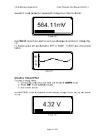
Page 13: ...loscope like picture of Voltage Fig 17 To change speed turn jog dial button LEFT or RIGHT To EXIT press the job dial button O 5 5 Figure 17 Adjusting Voltage Offset To adjust voltage offset 1 Connect...

Page 14: ...e appears to be a malfunction during the operation of the device the following steps should be performed in order to isolate the cause of the problem 1 Check the battery 2 Review the operating instruc...

Page 15: ...y 1 in range 0 1R 5M Resolution 0 01R in range 0 10R Test Frequency 1 kHz Capacitance Range 10pF 499uF Accuracy 5 in range 20pF 1000uF Resolution 0 5pF in range 1pF 100pF Test Frequency 1 kHz C 1000pF...

Page 16: ...ailure of this meter within the warranty period CAN Inc undertakes to get the meter repaired free of charge Please hand over the meter to the dealer from whom you have purchased along with this WARRAN...

Reviews: