CAN CHECKED MFD28 Gen2 Manual Download Page 49

Rev 1.0 
 

49 

9.3.2.12


multi switch 

A m

ulti switch

 is a switch that can assume two or more states. This can be used, for example, to 

switch different boost levels or to configure the control of the ABS. This function can be used to 
emulate a rotary potentiometer, for example, with your data display. 


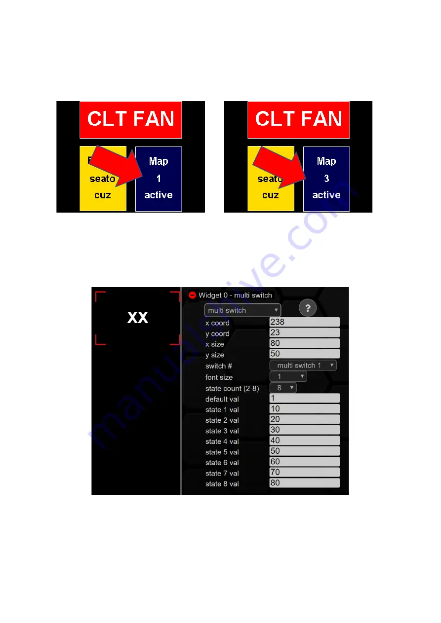
Figure 49: Keypad with two switches and one multi switch in different states 

Like all other widgets, the Multiswitch is configurable in size and number of states with our DSS. 

The 

multi switch

 can have up to eight different statuses. Like the can switch, you can also change the 

multi switch

 in position (x/y coord) and size (

x/y size

).  


Figure 50: Configuration multi switch 

You can create the number one to four and, to control the Haldex, a fifth multiswitch. 

Font

 size 

configures the font size, 

state count

 defines how many states the 

multi switch

 can accept.  

Default

 val 

the state when starting the displays and state 

x val

 the values of the corresponding states. 

The last (fifth) multiswitch is for the Haldex widget. To do this, you first need a Haldex license. 
Contact your dealer to purchase a Haldex license for Gen1 and Gen2. 


Summary of Contents for MFD28 Gen2

Page 1: ...MFD28 32 Gen2 Manual...

Page 2: ...otocol 13 5 2 6 Can Switch 13 5 2 7 Timeout 13 5 3 Sensor Init 13 5 4 License 14 5 5 Gears 15 5 6 Splash Screen 16 5 7 Start Page 16 5 8 Shiftlight 16 5 9 Dim Sensivity 16 5 10 Pages 16 5 11 Custom Bu...

Page 3: ...sensor value 44 9 3 2 9 Gear 46 9 3 2 10 G meter 47 9 3 2 11 can switch 48 9 3 2 12 multi switch 49 9 3 2 13 horizontal bar 50 9 3 2 14 Needle 51 9 3 2 15 Overlay 53 9 3 2 16 Pixel 54 9 3 2 17 perform...

Page 4: ...Display remains black and white 72 11 4 I don t get any data no can 72 11 5 Gear indicator does not work 73 11 6 Yellow bar at the bottom of the data display 73 11 7 My Performance Meter runs permanen...

Page 5: ...der adapter CANchecked stickers One USB cable and either two Molex connectors 8 pin and 10 pin and a choice of different pre crimped leads and two 1kohm resistors or a pre terminated OBD cable Your di...

Page 6: ...igure 1 MFD28 32 Pinout Of course CanH and CanL are not necessarily necessary for operation Via the four analog inputs AINs analog inputs you can also feed the 0 5 volt voltages of analog sensors into...

Page 7: ...he supplied USB cable We recommend leaving it connected to the display and hiding the USB plug in an easily accessible place In this way easy access to your data display is possible at any time withou...

Page 8: ...the page change you will be shown in yellow in a cutscene which page you are on If you switch to a blank page the display in yellow font on a black background Page is empty indicate Figure 3Appearance...

Page 9: ...ke all settings relevant for the operation of the display The menu navigation in the setup is described in chapter5 Figure 4 Setup and Quick Access Bar If you swipe your finger from bottom to top purp...

Page 10: ...If you press the green button again the log will end The display counts the logs up to 255 and then starts again at 0 This number is not customizable On the SD card in the folder logs you will find t...

Page 11: ...avigation and the submenus of the setup Each point of the setup is processed in a subchapter The setup can always be terminated by clicking on the white X on a red background Figure 6 Setup In the sub...

Page 12: ...o five seconds are possible ATTENTION Depending on the protocol used OBD TP2 UDS BMWE BMWF the display only queries the sensors queried on the current page If for example a popup for the exhaust gas t...

Page 13: ...e necessary for example to access the ECUs via a diagnostic tool For later operation of the data display however the protocol must then be reactivated 5 2 6 Can Switch Your Gen2 data display can not o...

Page 14: ...widget N A Gear Sensor in TRI TRX File for Gearwidget Gear Gear Mode Sensor in TRI TRX File for Gearwidget Automatic Gear Mode Manual N A Figure 9 Sensor Init In addition to the settings of the essent...

Page 15: ...ed as follows 1 To enter the gear ratios simply click on the corresponding gear and then enter your gear ratio there via the opening keyboard Figure 11 Gear device To save you time nerves and a calcul...

Page 16: ...ivation speed threshold for each of the eight switching flash LEDs by tapping them Furthermore you can set the speed threshold RPM flash at which all eight LEDs start flashing Other menu items are the...

Page 17: ...The user interface can be aligned in all four spatial directions Horizontal vertical horizontal2 and vertical2 are available as options After a change a restart of the display is necessary This can be...

Page 18: ...reated in the TRI TRX file will oscillate between their minimum and maximum value For example you can use this feature to show your friends how cool your new data display is However this function is p...

Page 19: ...xt editor you will find the following structure Each line represents a sensor and all metadata associated with the sensor These 25 metadata are in columns separated by semicolons The decimal separator...

Page 20: ...NTC 3 constants and pull up resistor Steinhart Hart 14 MapperInfo1 Varies by mapper type 15 MapperInfo2 Varies by mapper type 16 MapperInfo3 Varies by mapper type 17 MapperInfo4 Varies by mapper type...

Page 21: ...rmware O ABC X TRX the TP2 protocol is used with the TP2 firmware T ABC X TRX Vehicles that allow UDS protocol use the UDS firmware U ABC X TRX BMW E F series for vehicles of the E and F series B ABC...

Page 22: ...data display so that the files of the desired protocol are hidden see chapter 6 2 The desired TRI TRX files are not on your SD card and must be added later You have two options for adding the files to...

Page 23: ...zontal bar MinValue MaxValue zugeordneter Sensor needle MinValue MaxValue zugeordneter Sensor theverlay MaxValue zugeordneter Sensor performance meter Zugeordneter Sensor It is not possible to change...

Page 24: ...e three layers round meter overlay and sensor value on the DailyDash With the DailyDash are not only three layers above the large boost pressure display but also above the three small round displays a...

Page 25: ...nterface shown in the image below Figure 17 CANchecked Updater After inserting your display your PC Mac should recognize the display and automatically identify it as an available device in the updater...

Page 26: ...display restarts exception when installing an init file here the display only starts again after installing a regular software Must only be installed when the data display is no longer accessible and...

Page 27: ...dows 7 here As soon as you have installed the DSS you can execute it should be able to see the following start screen and click on the CANchecked logo to get to the selection field of the device to be...

Page 28: ...tablish the connection by clicking on it Attention After plugging in the USB cable please wait until the start animation has run through on the display before the connection is established in the DSS...

Page 29: ...set you can call up an overview of all pages in the Pages tab More on this in chapter 9 3 If the second selection field is checked the TRI Editor is emptied before the sensors are imported from the d...

Page 30: ...d into five sections Figure 23 Buttons in the TRI editor In the first area you can import sensors from different data formats into the editor Possible formats are DBC Files TRI Files OBD2 PIDs lbl Fil...

Page 31: ...ion to the min and max warning values you can also assign change the names of your sensors maximum 15 characters no special characters and switch popups for the warning values on and off After you hav...

Page 32: ...or in enhanced mode In addition you now also have the remove and copy buttons to choose from with which you can delete and copy can addresses and sensors This function is especially handy when creatin...

Page 33: ...w of the pages by clicking on them In addition to hiding individual pages in the display setup on the data display itself you can also hide or make visible the pages in the overview page by ticking th...

Page 34: ...helper lines Projects auxiliary lines into the DSS for easier arrangement of widgets via drag and drop clear view Deletes the currently loaded page in the DSS and lets you start on a blank screen load...

Page 35: ...he names and a preview of the corresponding pages displayed and can load them into the DSS by double clicking So far you can choose from these views AirflowLogging BasicLogging4cyl BasicLogging5cyl Ba...

Page 36: ...u uncheck a widget in blue the widget will be made invisible in your preview in the DSS You can use this function to create widgets in different layers in the same place without accidentally clicking...

Page 37: ...coordinates 320 240 You can either drag and drop individual widgets with the mouse or select them with the mouse and then arrange them with the arrow keys Depending on the type a sensor must be assign...

Page 38: ...he outer circle you specify the base color in the inner square the brightness or darkness The color is then always written as hexadecimal code in the corresponding field of the widget and can be marke...

Page 39: ...m top2bottom Horizontal line as pointer bar Furthermore a colour for the lower values and a colour for the upper values can be defined For optimal design of the display area the lower or upper limit o...

Page 40: ...ed in size and position offset As with the vertical bar the min value and max value functions can be used to set the values for the start and end of the round meter The position of the start and the e...

Page 41: ...can be assigned to each diagram If several sensors are to be displayed simultaneously in one window several YT diagram widgets must be superimposed Figure 36 Configuration YT diagram A delay can be i...

Page 42: ...ze of the displayed plain text via the font function Here you can set font sizes from 0 9 where 0 is the smallest and 9 is the largest As with other widgets before you can set the font color via colou...

Page 43: ...us rectangle widget states of sensors can be mapped here using logical operators To beautify the pages the same color must be assigned to both states so that the icon is displayed permanently and inde...

Page 44: ...value red background or falling below the min value blue background can also be activated individually for the widget Figure 41 Display view of the sensor value widget with frame You can adjust the nu...

Page 45: ...r set at low warn colour when falling below the min value in the TRI TRX file max warn activates the color set at high warn colour when the max value is exceeded in the TRI TRX file centered centers t...

Page 46: ...the gear P R N D S Important for the error free function of this widget is the correct assignment of the sensors in the sensor init 5 3If gear mode is not assigned in the sensor init only the gear is...

Page 47: ...rove your lap times or verify your aeromods Figure 45 G meter as predefined page If your TRI TRX file has the sensors for lateral and longitudinal acceleration you can use the Gmeter With this widget...

Page 48: ...ve Figure 47 Keypad with two switches yellow inactive green active and one multiswitch If desired a pop up inform window can be activated in the DSS when switching the switches This then appears brief...

Page 49: ...ith our DSS The multi switch can have up to eight different statuses Like the can switch you can also change the multi switch in position x y coord and size x y size Figure 50 Configuration multi swit...

Page 50: ...From right to left Vertical line as pointer Furthermore a color for the lower values and a color for the upper values can be defined For optimal design of the display area the lower or upper limit of...

Page 51: ...ou can see the peak of the last milliseconds function can be deactivated in the DSS Please put the matching speedometer disc as a picture With x y coord you can adjust the position of the widget as us...

Page 52: ...d in the round meter in degrees where 0 degrees is at 12 o clock For example if you want a classic 6 o clock speedometer your min value is 0 and the start angle is 180 As already known from the round...

Page 53: ...ency of 60 Hz as soon as the warning threshold 6000 rpm is exceeded Figure 55 overlay widget in both states on the TrackView Depending on which sensor you assign to the widget it can be used as a swit...

Page 54: ...ying these sensors as widgets round meter sensor value etc on your new page you can create the pixel widget twice Once for the sensor lambda and once for the sensor speed Now these two sensors are add...

Page 55: ...d A correction due to slope gradient and tailwind or headwind does not take place A representation of the form meter can be found in the figure below Figure 58 Display view of the performance meter Li...

Page 56: ...and size x y size Each of the two states can be assigned a color or a gradient using the color wheel In the example below the widget is used to map the state of cruise control If a 10 status value is...

Page 57: ...e lines to spatially separate your ads You can also use it to create backgrounds for other ads In the figure below the rectangle was used to sketch the maximum deflection of the vertical bar above Fig...

Page 58: ...um of 32 characters is allowed per text field Several text fields can be created per page In the example below the background of the widget has been colored blue with the color wheel bg colour and the...

Page 59: ...ze for icons is 30x30 pixels for smaller logos 100x40 pixels is recommended If the desired image has been scaled appropriately and uploaded via the upload section and then be selected from the drop do...

Page 60: ...ing on a sensor As with the picture widget the colours of the image can be mixed or cropped using blend colour alpha blend and ignore colour min value defines the lower threshold value for starting an...

Page 61: ...er sensors can also be assigned to this widget with the Gen2 For example it is possible to show or hide images logos based on the accelerator pedal position Attention you can only use one image for RP...

Page 62: ...oad button Figure 68 Overview Log Viewer Once you have opened a log the diagram will be displayed on the left half of your screen and the available sensors on the right half Now you can select the sen...

Page 63: ...e Further menu items are backlight Backgrounds light the sensitivity of the dimming Dim sensitivity the orientation of the display 9 5 2 Can Bus As in the menu on the data display itself you can de ac...

Page 64: ...nctions PageSwitch Brightness and Frequency In can be assigned and activated Figure 73 IO pins Via PageSwitch the side of the data display can be switched to the next by closing to ground on one of th...

Page 65: ...e two sensors into a common output In the example below a value between 0 and 100 is generated from the speed and accelerator pedal sensors depending on the condition This value can be used for exampl...

Page 66: ...you can link sensors together through logical functions You can add subtract multiply and divide from the basic arithmetic operations with up to five variables sensors or fixed values Choose a total...

Page 67: ...ur data display In order to use the Math Channel as output it must be created as an internal sensor in the TRI editor 9 5 10 Boost PWM Control In this menu the paid item Boost PWM Control Addon can be...

Page 68: ...ned as axis scaling sensor 9 6 Upload In the upload section of the DSS you have the possibility to transfer files to your data display By clicking Choose File you can search your computer for files an...

Page 69: ...licking on Start Log the received Can Bus data is displayed The stop is done via the same button Clear Log deletes the Can Log 9 8 Work offline The data display does not need to be permanently connect...

Page 70: ...ile does not yet have a sensor for an analog input you can add it to your TRI TRX file as described in chapter 9 2 via the add sensor internal button by selecting the corresponding AIN s scrolling dow...

Page 71: ...he pull up resistance If you only have three data points the calculation tool will help you with one click on calculate While you re at it you can directly assign the min and max values of your sensor...

Page 72: ...roblem and discuss further steps 11 3 Display remains black or white If your display is suddenly only black or white and no longer starts as usual please carry out a software update as described in ch...

Page 73: ...sor init5 3 Under Setup Gears5 5 The widget itself is created incorrectly delete via DSS9 11 6 Yellow bar at the bottom of the data display If images are missing on a page that are created in the layo...

Page 74: ...The files with the names logo00 bmp to logo19 bmp are located in the pic folder You have two options for changing but no matter which one you choose you have to convert your desired start animation vi...

Page 75: ...te this page manually on the display and then create it again To delete the page please navigate to Setup Pages and enable and disable the page where it always hangs a few times Then you will see the...

Reviews: