background image

36”

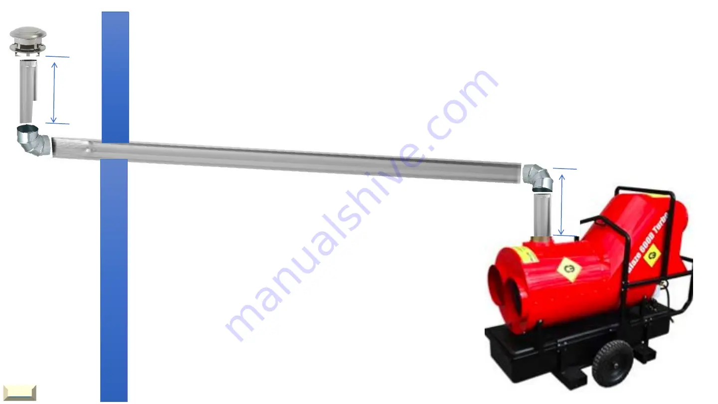
Best practices for venting when heater is located inside a building 

Avoid using as many 90-degree elbows as possible

Venting runs should be as short as possible

Vertical rise minimum 3 feet, 5 feet is better outside the building.

Always install a rain cap.

Never decrease diameter of flue piping.

Horizontal runs ¼” per foot rise.

Make sure all piping is properly secured.

Make sure there is no negative pressure inside 
the building where the heater is placed. 

Note: 

where the vent pipe passes through 

a combustible wall a fire proof thimble 
must be used.

40

36”

HOME

Summary of Contents for Blaze EB400G

Page 1: ...chnicians in the field We ve supplied issues and solutions to the most common problems encountered in the field If you need assistance while troubleshooting on the job they are easy to store in your smart phone tablet or computer Getting Started is easy Just click on Page for the problem you are encountering Contact Us Page 30 Tech Tips and Bulletins for you Page 31 Quick set up and Installation G...

Page 2: ...t goes through the 60 second purge but doesn t ignite Page 3 You Reset the Burner Control The Burner motor Does Not Start and the Burner Control Locks out on Reset Page 10 You Reset the Burner Control but the reset light is solid red during the pre purge and the control locks out on reset Page 13 You Reset the Burner Control and after the pre purge the burner fires up but the flame goes out after ...

Page 3: ...port of the gas valve Reset the burner control After the 60 second purge check to see if gas pressure is coming through the valve Keep a close eye on the manometer as the pressure will only register for 1 or 2 seconds after the 60 second pre purge NOTE If gas pressure is present Page 4 If gas pressure is NOT present Page 6 3 HOME ...

Page 4: ...If gas pressure is present Test the components Page 5 Defective igniter Defective ignition cable Broken electrode 4 3 5 HOME ...

Page 5: ...the ignition cable to the igniter Ensure the gas gun is WELL GROUNDED to the burner housing when testing for spark Reset the burner control and check for spark after the pre purge Keep a close eye on the electrode as the spark will only appear for 1 second AFTER the 60 second pre purge Ignition Cable Electrode Gap 1 8 No spark indicates a defective igniter SHUT OFF the gas supply to the burner bef...

Page 6: ...If gas pressure is NOT present ON OFF switch is in the OFF position Defective 24v Transformer Defective Burner Control Defective gas valve Test the components Page 7 6 HOME ...

Page 7: ...Checking the ON OFF switch Continue to Page 8 7 Ensure the switchover valve is in the proper position for LP OR NG Ensure the gas valve switch is in the ON position HOME ...

Page 8: ...Checking the 24 volt transformer Check black and red stripe wires on 6 prong plug For 24 volts If 24 volts is NOT present the transformer is defective If 24 volts is present Page 9 8 HOME ...

Page 9: ...ol After the 60 second purge check for 24 volts on the white and violet wires on the 6 prong plug If 24 volts is present after the 60 second purge the gas valve is defective If 24 volts is NOT present after the 60 second purge the burner control is defective 9 HOME ...

Page 10: ...er control The burner motor does not start and the burner control locks out on reset Defective burner motor Defective Burner Control Defective Motor Relay Test the components Page 11 10 Light Flashing reset control HOME ...

Page 11: ...ol Reset burner control then check for 120 volts on burner motor relay coil If 120 volts is NOT present defective burner control If 120 volts is present defective burner motor relay OR burner motor Checking burner motor and motor relay Page 12 11 HOME ...

Page 12: ...motor and motor relay continued Reset the burner control and check for 120 volts going to the burner motor If 120 volts is present defective burner motor If 120 volts is NOT present defective burner motor relay 12 HOME ...

Page 13: ...light is solid red during the purge and the control locks out on reset The air proving switch is defective The air hose is cracked or busted 13 Note The air proven switch contact must be open to start and close after the burner motor starts HOME ...

Page 14: ...ge the burner fires up but the flame goes out after 5 or 10 seconds The flame rod is defective or dirty Flame rod lead wire is defective 14 Clean or replace flame rod and wire NOTE do not use sandpaper to clean flame rod A cloth will be sufficient HOME ...

Page 15: ...n Reset and will not start Page 16 If the Circulating Fan Fails To start Page 23 If the fan is starting intermittently erratically or inconsistently Page 24 Circulating Fan Does Not Shut Off Page25 15 The Burner is NOT locked out on reset HOME ...

Page 16: ...r Control is NOT locked out on Reset and will not start Check for 120 volts between Terminal L1 and Common L2 on the burner control If 120 volts is present Page 17 If 120 volts is NOT present Page 19 L1 L2 16 HOME ...

Page 17: ... Defective Bypass Switch Defective Burner Control If 120 volts is PRESENT on burner control Test the components Page 18 Jump TR TW 17 HOME ...

Page 18: ...d burner control To check the bypass switch place a jumper wire on terminals TR TW If the burner starts the bypass switch is defective If the burner does not start the burner control is defective Jump TR TW Terminals TR TW 18 HOME ...

Page 19: ...150 F Defective Thermocouple Defective Temperature Controller Defective Fan Motor Thermostat Switch 19 Test the temperature controller Page 20 Thermal Limit Disc Temperature Controller Thermostat Switch Inside Fan Motor Thermostat Switch Sealed Inside Fan Motor Not serviceable Thermocouple HOME ...

Page 20: ...f 120 volts is NOT present the temperature controller is defective If voltage is present the 150F thermal limit disc is defective or the thermal heat thermostat in the fan motor is defective Page 21 NOTE If the display on the temperature controller is reading 000 or other false reading the thermocouple Is defective HOME ...

Page 21: ...t 21 Test for 120 volts on each terminal of the disc to ground If 120 volts is NOT present the fan motor temperature switch is defective If 120 volts is present on only 1 terminal of the disc the disc is defective Test the motor thermostat Page 22 HOME ...

Page 22: ...rmostat is wired in series with the 120 volt limit and temperature controller circuit Check to ensure the thermal heat thermostat contact is closed by testing for continuity using the 2 white or 2 grey wires leading to the circulating fan motor If the contact is closed the thermal heat switch is good If the contact is open the Circulating Fan Motor is defective and needs to be replaced HOME ...

Page 23: ...N position check for 120 volts on the fan relay R1 on the fan motor terminal Blue wire If there is 120 volts the circulating fan motor is defective If there is NO voltage the relay is defective If the circulating fan fails to start 23 HOME ...

Page 24: ...F Disc is over 110 F and the fan does not start the 110ºF fan disc is defective Note It is very unlikely that all 3 components would be defective at the same time If the circulating fan fails to start likely it would be the circulating fan motor or the R1 relay The EB400D is equipped with redundant controls to ensure positive starts for the circulating blower fan If the fan is starting intermitten...

Page 25: ...n the ON position Turn it to the OFF position Defective 110ºF fan disc Defective fan relay Defective temperature controller 25 Fan 0veride Switch Testing the components Page 34 First ensure that the ambient temperature at the 110ºF fan disc is less than 80ºF HOME ...

Page 26: ...t off Checking 110ºF fan disc Note If 120 volts is present on BOTH terminals the disc is defective If 120 volts is present on ONE terminal only the disc is GOOD Page 35 Check for 120 volts between ground and each terminal 26 HOME ...

Page 27: ...rculating fan does not shut off Checking circulating fan relay Check for 120 volts on the relay coil terminals 0 volts indicates a defective relay If 120 volts is present on the relay coil Page 36 27 HOME ...

Page 28: ...ing temperature controller and thermocouple If the circulating fan 110 F disc is good AND there is 120 volts on the circulating fan relay R1 coil Defective temperature controller Defective Thermocouple 28 Testing the components Page 37 HOME ...

Page 29: ...red and white thermocouple wires from the back of the temperature controller 2 Install a jumper wire between the two terminals If the fan stops running the thermocouple is defective If the fan continues to run the temperature controller is defective thermocouple wires Caution do not remove the wrong red and white wires 29 HOME ...

Page 30: ...We pride ourselves in offering The best technical support in the industry sales campoequipment com 1 866 323 0042 Here To Help 30 HOME ...

Page 31: ... Member As a member you will receive updates and notifications of any changes to the Guides As a member you will be notified of upcoming courses As a member you will be first to receive any new Field Assist Troubleshooting Guides As a member you will receive more Tips to make your job easier It s quick simple and easy join us today Click HERE to access the membership card 31 HOME ...

Page 32: ...Tech Tips And Bulletins and more for You Replacing the thermocouple made easier Page Not Available yet Using a Combustion Analyser Page 38 Replacing circulating fan motor Page Not Available yet 32 HOME ...

Page 33: ... Adjusting proper gas pressures Page not available Yet Electrical hook up Page not available Yet Gas Piping Page not available Yet Venting the heater Page 39 Adjusting the burner combustion Page 38 Gas train test ports and adjustment locations Page 42 HOME ...

Page 34: ...rge all air from gas lines connected to the regulator Soap test all gas lines and fittings including gas train for leaks WARNING If the heater is going to be fed with power from a generator always have the heater unplugged until the generator is running stable Ensure the generator is sized to accommodate the heater voltage demand Start up continued Page 35 34 HOME ...

Page 35: ...Combustion Analyzer Voltmeter Manometer What you need to commission the heater Help us Help you Instruments for heater set up and diagnostics 35 Start up continued Page 36 HOME ...

Page 36: ...e charts to help them determine this information Determine if unit will run on Natural gas or Propane Make sure that NG LP switchover valve is in the right position Make sure the incoming gas pressure is between 7 and 14 WC Make sure the venting is properly installed Make sure the proper voltage is supplied to the heater Make sure the proper size wiring is connected to the heater Switch over valve...

Page 37: ...witch to OFF position Place the toggle switch in bypass position to start the burner Once the burner is running make sure that incoming pressure is between 7 and 14 of WC If the pressure drops out when running it means that there is not enough volume of gas or not enough pressure Adjusting the burner for proper combustion Page 38 If the gas pressure drops make sure the gas regulators and piping ar...

Page 38: ...ive this open or close the air adjustment on the burner Page 41 Note Opening the air adjustments will increase the o2 levels and closing the air adjustments will decrease the o2 levels Using a combustion analyzer Page 43 Adjusting the burner for clean and reliable combustion 38 HOME ...

Page 39: ... on the flue pipe Make sure that flue gases are not being circulated into by the cooling fan and pushed into the space you are heating 36 WARNING The appropriate measures must be taken to ensure there will be no positive pressures on the exhaust flue of the heater Venting from inside a building Page 40 39 HOME ...

Page 40: ...minimum 3 feet 5 feet is better outside the building Always install a rain cap Never decrease diameter of flue piping Horizontal runs per foot rise Make sure all piping is properly secured Make sure there is no negative pressure inside the building where the heater is placed Note where the vent pipe passes through a combustible wall a fire proof thimble must be used 40 36 HOME ...

Page 41: ... are indicated in manufactures instructions as Example 6 2 the first number being the shutter and the second number being the band Band Shutter Note recommend air settings are approximate and will change with altitude and fuel oil temperature The Use of a combustion analyzer will ensure clean burning and maximum efficiency 41 HOME ...

Page 42: ...ain Blaze 600 700 1000 NOTE Gas Train for the EB200G and EB400G page 44 Outlet pressure port inlet pressure port Pressure regulator adjustment under cap Switch over valve Gas solenoid valve test port 42 HOME ...

Page 43: ... probe into the flue stack hole Adjust air settings on burner until you have an Oxygen reading between 3 to 4 Check to ensure that your CO Carbon Monoxide levels are no higher than 0 50 PPM Start up complete While the flue stack is cold pre drill a 1 4 hole in the flue stack 18 above the heater flue collar HOME ...

Page 44: ...Gas Train EB200G and EB400G Gas valve On Off Switch 44 Switchover valve for LP OR NG Test outlet port Test Inlet port HOME ...

Reviews: