


TE525 Tipping Bucket Rain Gage
TE525
TE525WS
TE525MM
Height
24.1 cm (9.5 in)
26.7 cm (10.5 in)
29.2 cm (11.5 in)
Tipping Bucket Weight
0.9 kg (2 lb)
1 kg (2.2 lb)
1.1 kg (2.4 lb)
Cable
2-conductor shielded cable
Cable Weight
0.1 kg (0.2 lb) per 10 ft length
7. Operation
7.1 Wiring
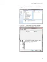
When Short Cut is used to generate the datalogger program, the sensor should
be wired to the channels shown on the wiring diagram created by Short Cut.
The rain gage is typically wired to a datalogger’s pulse channel (see TABLE
7-1).
TABLE 7-1. Wiring for Pulse Channel Input
Color
|
Description
CR800
CR850
CR1000
CR3000
CR5000
CR9000(X)
CR510
CR500
CR10(X)
21X
CR7
CR23X
CR200(X)
Series
Black Signal
Pulse
Channel
Pulse
Channel
Pulse
Channel
P_SW
White Signal
Return
G
Clear Shield
G
Dataloggers listed in TABLE 7-2 have the capability of counting switch
closures on some of their control ports. When a control port is used, the return
from the rain gage switch must be connected to +5 V on the datalogger.
TABLE 7-2. Wiring for Control Port Input
Color
Description
CR800
CR850
CR1000
CR3000
CR500
CR510
CR10X
CR23X
Black Signal
Control Port C2/P3
Control Port Control Port
White Signal Return 5 V
5 V
5 V
5 V
Clear Shield
G
9


