1. Download Campbell Scientific’s collection of configuration templates from
https://www.campbellsci.com/downloads?c=9999&d=344
and run the
executable downloaded.
2. Connect a Windows ® computer to the RV50 using the supplied Ethernet cable.
3. Launch
Internet Explorer
® or
Firefox
® web browser, and enter
http://192.168.13.31:9191 into the address bar. The
ACEmanager
login screen
should appear in the browser.
4. Log in using
User Name
=
user
and
Password
=
12345
5. Click the
Template
menu button in the
ACEmanager
toolbar. A template
application window will appear. Browse to and upload one of the configuration
templates downloaded from Campbell Scientific.
Template File Name
Description
RV50_115200.xml
115200 baud RS-232, 10 Mbps Ethernet. The
most common template used. Use with
dataloggers such as CR300-series, CR800-
series, CR1000, CR3000, and CR6.
RV50_9600.xml
9600 baud RS-232, 10 Mbps Ethernet. Most
commonly used with older model dataloggers
such as CR200X-series, CR10X, and CR23X.
NOTES:
Campbell Scientific templates reduce power consumption by changing LED
behavior to report activity and errors only.
Default port numbers- Serial Server: 3001, PPP Pakbus: 6785
6. Click
WAN/Cellular SIM Slot 1 Configuration
. Enter APN provided by cellular
provider into
User Entered APN
. See manual for common examples.
7. Reboot the RV50 after successfully applying the configuration template. Do
this by clicking the
Reboot
button in the
ACEmanager
toolbar, by momentarily
pressing the
Reset
button (2 seconds), or by temporarily removing power from
the RV50.
8. Log in again. Check the
Status Network State
field. It should read ‘Network
Ready,’ indicating the RV50 is connected to the cellular network. The RV50’s
connection to the Internet can easily be tested by selecting the
Admin |
Advanced
tab and using the
PING
tool to ping an Internet server, such as
www.campbellsci.com
.
With the appropriate RV50 template applied and the RV50 connected to the
datalogger
RS-232
or
CS I/O
port, most dataloggers do not require any further
configuration. If
PPP
or the
Ethernet
port is used, additional configuration of the
RV50 and the datalogger is required. See the RV50 manual for more information.
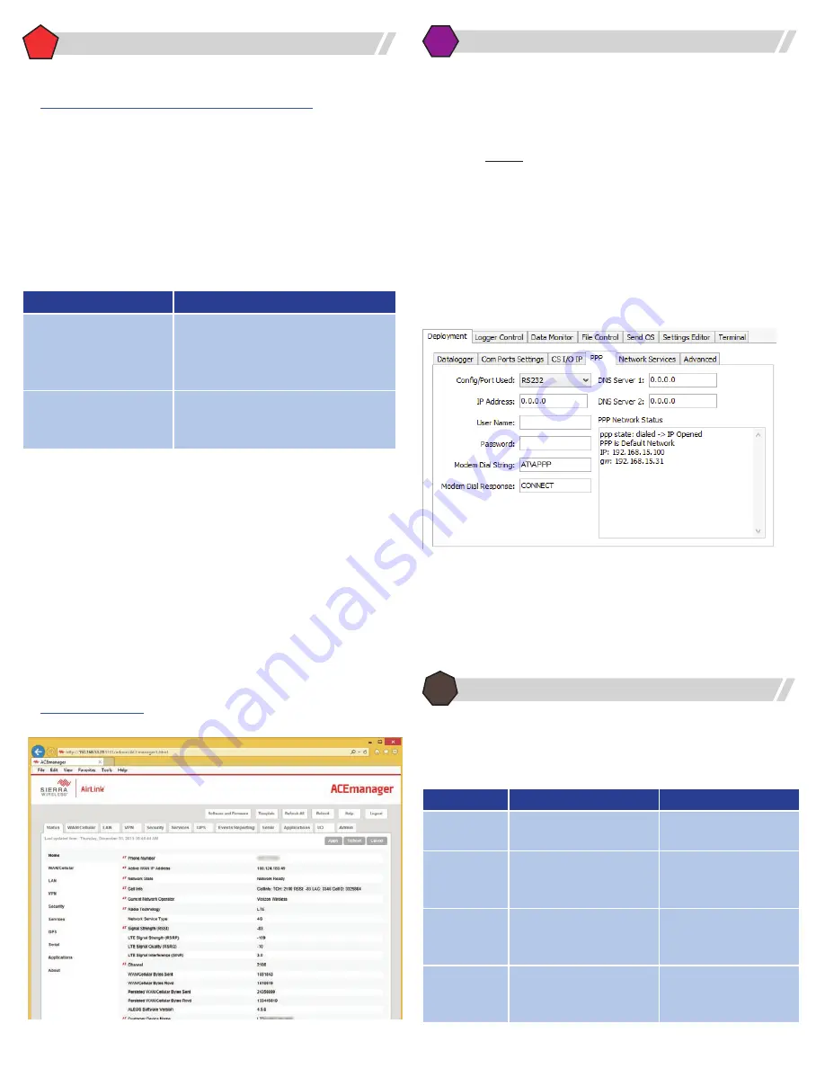
The RV50 has optional PPP support for the datalogger’s PPP and Internet protocol
capabilities such as Email, FTP, HTTP, etc. This applies to the CR300-Series, CR800-
Series, CR1000, CR3000, and CR6 connected via RS-232 or CS I/O. To enable PPP in
the datalogger:
1. Connect to the datalogger using Campbell Scientific’s Device Configuration
Utility (
DevConfig
).
2. On the
Deployment
|
PPP
tab, change:
a.
Config/Port Used
to the datalogger serial port that will be connected to
the RV50 RS-232 port. A common selection is RS232.
b.
Modem Dial String
to
AT\APPP
3. On the
Deployment
|
ComPorts Settings
tab, select the datalogger serial
port that will be connected to the RV50 RS-232 port and change
Baud Rate
to
115.2k Fixed. This is done to match the configuration of the RV50.
4. Using the
Deployment
|
Network Services
tab, protect the datalogger by
disabling any services that are not required. Common examples include FTP,
HTTP, and Telnet.
Dataloggers can be connected in a variety of ways to suit the needs of the
application. Common methods include the use of one of the following serial or
Ethernet peripherals.
Datalogger
Serial
Ethernet Cable
CR200X-Series,
CR300-Series
• 18663 RS-232 null modem
• NL201 RS-232
CR800-Series
• 18663 RS-232 null modem
• 17855 C-port cable
• SC105 CS I/O to RS-232
• NL201 RS-232 or CS I/O
CR1000, CR3000 • 18663 RS-232 null modem
• 17855 C-port cable
• SC105 CS I/O to RS-232
• NL116 or NL121
• NL201 RS-232 or CS I/O
CR6-Series
• 31055 CPI/RS-232 cable
• 17855 C-port or U-port cable
• SC105 CS I/O to RS-232
• Direct to Ethernet
• NL201 RS-232 or CS I/O
6
Configure the Datalogger
Connecting Sensors
7
Connect the Datalogger to the RV50
5
Configure the RV50 Using ACEmanager


