background image

SDMS-30 Multipoint Scanning Snow Depth Sensor 

16 

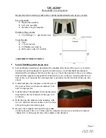
FIGURE 11-2.  SDMS-30 Mounting Angles 

TABLE 11-1 SDMS-30 Mounting Procedure 

Step 

Procedure 

Attach the L shaped mount to the flat back mount using the common hole and crescent 
shaped screw holes. 

Using Figure 11-2, decide which angle your sensor is to be mounted at. 

Bolt the L shaped mounting piece to the underside of the sensor. The big middle circle should 
line up with the cable connector. 

Install sensor and mount 1 meter above maximum seasonal snow depth height. For mounting 
to poles, use thin hose clamps.  

Line up the connector end of the cable to the cable connector on the sensor. Lightly push the 
connector into place and screw the connector to secure.    

Screws 

Screw 
Holes 

Summary of Contents for SDMS-30

Page 1: ...INSTRUCTION MANUAL SDMS 30 Multipoint Scanning Snow Depth Sensor Revision 01 17 C o p y r i g h t 2 0 1 6 C a m p b e l l S c i e n t i f i c C a n a d a C o r p...

Page 2: ......

Page 3: ...under guarantee or not Please state the faults as clearly as possible and if the product is out of the guarantee period it should be accompanied by a purchase order Quotations for repairs can be give...

Page 4: ......

Page 5: ...protection and take other appropriate safety precautions while working on or around tripods and towers Do not climb tripods or towers at any time and prohibit climbing by other persons Take reasonabl...

Page 6: ......

Page 7: ...digital cell phones and aerials may also not be applicable according to your locality Some brackets shields and enclosure options including wiring are not sold as standard items in the European marke...

Page 8: ......

Page 9: ...tions 5 6 Operation 6 6 1 SDI 12 Command List 7 6 2 RS 232 RS 422 Command List 8 7 Wiring 9 7 1 Powering Up 10 8 Calibration 10 8 1 Automatic Calibration 10 8 2 Manual Calibration 11 9 Updating Firmwa...

Page 10: ...ABLE 4 2 Set up Wiring for RS 232 5 TABLE 7 1 Firmware Update Wiring 9 TABLE 7 2 Power Wiring 9 TABLE 7 3 SDI 12 Wiring 9 TABLE 7 4 RS 422 Wiring 10 TABLE 7 5 RS 232 Wiring 10 TABLE 10 1 Wiring for Fi...

Page 11: ...re implemented to provide a reliable measurement in various weather and surface conditions The size of the target area on the surface of snow varies depending on the height and the tilt angle of the S...

Page 12: ...4 screws 2 lock washers 2 band clamps mounting bracket 4 lens wipes a ResourceDVD and the Female DB9 terminal block 4 QuickStart 4 1 Set Up Using SDI 12 Use Table 4 1 when setting up an SDMS 30 to com...

Page 13: ...gger TX C1 4 Connect the Yellow wire to a datalogger RX C2 5 Connect the Brown wire to ground G 6 Apply power to your sensor 7 Send sample RS 232 datalogger program as seen in Section 10 1 RS 232 Samp...

Page 14: ...ation Protocols SDI 12 RS 232 RS 485 General Operating Temperature 40 C to 50 C Weight 1 8 kg 3 9 lbs Enclosure Protection Class IP68 Laser Safety Class 2 With sensor heater on Dimensions Height 12 cm...

Page 15: ...rouped in 8 packets aR0 depth Similar to aD0 for continuous measurement mode aXA Perform automatic calibration to determine installation angle and height aXIx Where x is the desired interval Set the m...

Page 16: ...t in mm n a Manually set the current sensor height in millimeters This option would only be used if the automatic calibration fails due to problems in the target area g xx Where xx is the existing sno...

Page 17: ...the sensor Table 7 1 Table 7 2 and Table 7 3 outline assignments of wires of the connecting cable Use proper tools to connect the wires to the datalogger and other devices TABLE 7 1 Firmware Update Wi...

Page 18: ...and wiring of the SDMS 30 are done Section 11 Mounting and Section 7 Wiring apply power to the SDMS 30 8 Calibration Once the SDMS 30 is fully installed calibrate it for proper operation Calibration...

Page 19: ...nd the sensor will ask to confirm the request Enter y to proceed 9 Updating Firmware To update the firmware of the sensor download the firmware available on the website http www campbellsci ca sdms 30...

Page 20: ...he folder Figure 9 2 8 Browse the files on the PC using the button Select the cpp hex firmware file from the folder 9 From the Device dropdown select SDMS 10 From the COM Port dropdown select the COM...

Page 21: ...ostic variables Public PTemp batt_volt Units PTemp deg C Units batt_volt volts Variables for WeatherPia SDMS30 Scanning Laser Sensor Public SDMS30_Measure_Now As Boolean the user can set this to TRUE...

Page 22: ...ight SDMS30_string_temp 1 0 Scan 10 Sec 5 0 PanelTemp PTemp _60Hz Battery batt_volt The user s programming for other sensors would go here in the main scan NextScan SlowSequence Scan 1 min 5 0 If SDMS...

Page 23: ...SplitStr SDMS30_string_temp SDMS30_string R 1 4 SplitStr SDMS30_Distance_Points SDMS30_string_temp 36 0 EndIf EndIf CallTable SnowDepth NextScan EndProg 11 Mounting The SDMS 30 is designed to be envir...

Page 24: ...cide which angle your sensor is to be mounted at 3 Bolt the L shaped mounting piece to the underside of the sensor The big middle circle should line up with the cable connector 4 Install sensor and mo...

Page 25: ...x the inclination angle by tightening the screw though the SDMS 30 part and the bracket part Lastly completely tighten the common hole screw See Figure 11 2 for mounting angle options 12 Maintenance W...

Page 26: ...W Edmonton Alberta T5L 4X4 CANADA www campbellsci ca dataloggers campbellsci ca Campbell Scientific Centro Caribe S A CSCC 300N Cementerio Edificio Breller Santo Domingo Heredia 40305 COSTA RICA www c...

Reviews: