


SC105 CS I/O to RS-232 Interface
8
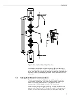
COM port of the computer. Once the emulator program is set up, testing can
proceed as follows:
1.
Disconnect the four conductor cables from the SRM-6A RAD modem at the
computer end. Jumper the XMT + to RCV + and jumper the XMT – to
RCV –. This creates a transmit loop which allows any key pressed at the
computer keyboard to be seen on the screen. If the key pressed is not seen,
check the following: COM port configuration, 25-pin cable from the
computer to the modem, and the RAD modem.
2.
Reconnect the four conductor cables to the modem at the computer end and
disconnect the cable from the modem at the datalogger end. Twist together
the XMT + wire and RCV + wire, twist together the XMT – wire and the
RCV – wire. Repeat step 1 by pressing a key on the computer keyboard. If
the key pressed is not returned, then the cable from the modem at the
computer to the datalogger modem is defective and will need to be repaired
or replaced.
3.
If steps 1 and 2 pass, the modem at the datalogger is suspect. Disconnect the
modem from the SC105 and bring the modem to the computer site. Attach
the modem to the computer, and repeat step 1 by jumpering the terminals of
the modem and pressing a key on the computer keyboard.
If the above tests pass and communication to the datalogger still has not been
established, perform tests 4, 5, and 6.
4.
A 12 V lead acid battery supply should not be discharged below 11.76 V. If
this occurs, the batteries will go into a deep discharge state and will need to
be replaced. The CR10 will function properly on a battery voltage of 10 to
15 volts. Check the 12 V supply with a voltmeter.
5.
On the wiring panel of most Campbell Scientific dataloggers there is a
terminal marked 5 V. Check the 5 V supply with a voltmeter. This 5 V
supply should be within a tenth of a volt. If not, it would indicate a problem.
6.
To verify that the datalogger and its serial I/O port are working, try to access
input memory locations using a laptop PC with the SC105 (using a null
modem cable connection). Configure the SC105 CS I/O Port to Modem
Enable for this test.
7.
If test 6 fails, use a CR10KD Keyboard Display to access input locations.
If the datalogger passes tests 4, 5, and 7, but fails test 6, then the SC105 is suspect
and will need to be repaired or replaced.
6.
CDMA Modem Application
In most modem applications, the SC105 can be used with the factory defaults.
This sets the SC105 up as modem enable 9600 baud, 8 data bits, Parity None and
1 stop bit. It also sets the DTR dead time to 2 seconds. This dead time is used to
prevent characters produce by the modem from waking the datalogger right after
communications has been terminated. The dead time can be adjusted by changing
the RS-232 DTR and RTS mode to Custom.
The CS I/O port configuration has several other modes that can be used depending
on the operating system used in the datalogger. These other modes offer
advantages for some applications. When using the PakBus OS, SDC 7, SDC 8,
SDC 10, or SDC 11 can be used. This allows communications from multiple
sources at the same time (for example, CDMA modem, RF400, and CR10KD).


