Appendix B. Installation Scenarios
B-6
Master
RF451
Slave 12
Slave 11
PC Running
LoggerNet
/PC400
Repeater
1
Slave/
Repeater
Slave 22
Slave 21
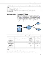
FIGURE B-7. Schematic of PC-to-RF Network with Parallel Repeaters
(using the SubNet ID)
TABLE B-3. RF451 Settings for Example 3
Master
Repeater
Slave/Repeater
Slave
11, 12 etc.
Slave
21, 22 etc.
Hardware
4
PC running
LoggerNet
,
RF451
RF451
CR1000,
RF451
CR1000,
RF451
CR1000,
RF451
Baud Rate
115.2K
115.2K
115.2K
115.2K
115.2K
Active
Interface
USB or RS-232
(to match how
LoggerNet
will
be
communicating
with the radio)
NA
CS I/O SDC
(with SDC
Address set to
an unused SDC
address on the
datalogger)
CS I/O SDC
(with SDC
Address set to
an unused SDC
address on the
datalogger)
CS I/O SDC
(with SDC
Address set to
an unused SDC
address on the
datalogger)
Radio
Operation
Mode
Multi-Point
Master
Multi-Point
Repeater
Multi-Point
Slave/Repeater
Multi-Point
Slave
Multi-Point
Slave
Repeaters
Used
Yes; check box Yes; check box Yes; check box Yes; check box Yes; check box
Network ID
1
1726
1726
1726
1726
1726
Frequency
Key
1
1
1
1
1
1
Receive
SubNet ID
NA
0
0
1
2
Transmit
SubNet ID
15 (default)
1
2
0
0
Summary of Contents for RF451
Page 2: ......
Page 6: ......
Page 10: ...Table of Contents iv ...
Page 34: ...RF451 Spread Spectrum Radio 24 ...
Page 36: ......
Page 46: ...Appendix B Installation Scenarios B 10 ...
Page 58: ...Appendix D Distance vs Antenna Gain Terrain and Other Factors D 10 ...
Page 60: ......
Page 61: ......


